Parent info
Parts you need
Affiliate links — we may earn a small commission
Try this circuit in your browser!
Run the code, press the buttons and watch what happens — before you buy any parts. No account needed.
Open in Simulator →Your classmates drew a graph. Yours changes in real time.
Imagine this: your Algebra class is learning about linear functions. Everyone draws y = 2x + 1 on graph paper. Neat lines, colored pencils, done.
You pull out a device with a 16×8 LED matrix. You text it: “m=3 b=-2” — and the LED grid instantly redraws the line with the new slope and intercept. You say: “As m increases, the line gets steeper. Watch.”
You change m from 1 to 5, live, in front of the class. Every student sees the slope change in real time.
That’s what we’re building. For about $28.
What you’ll need
| Part | What it does | Price |
|---|---|---|
| ESP32-S3-DevKitC-1 | Brain — calculates the function and drives the display | ~$12 |
| 8×8 MAX7219 LED matrix ×2 | 16×8 pixel grid for graphing functions | ~$10 |
| Breadboard + jumper wires | Wires everything together | ~$5 |
| USB-C data cable | Power + code upload | ~$5 |
You also need: home WiFi, Telegram account (free).
Total: ~$28 | Time: ~2–3 hours | Difficulty: ●●●○○
How it works (60 seconds)
A MAX7219 LED matrix is an 8×8 grid of LEDs controlled by a single chip. Two chained together give you 16 columns × 8 rows = 128 pixels. That’s your coordinate system.
The ESP32 calculates y = mx + b for every x value (0–15), converts the y result to a pixel row (0–7), and turns on that LED. When you send a new m or b value via Telegram, it recalculates and redraws instantly.
Think of it as a tiny graphing calculator — but physical, and you control it by texting it.
Step 0: Understand the math
The function y = mx + b has two parts:
- m (slope): How steep the line is. m=1 is 45°. m=2 is steeper. m=0 is flat. m=-1 goes downhill.
- b (y-intercept): Where the line crosses the y-axis (x=0).
On a 16×8 display:
- X axis: columns 0–15 (left to right)
- Y axis: rows 0–7 (we’ll flip so row 0 = bottom, row 7 = top)
- Origin (0,0) = bottom-left corner
For each column x, we calculate: row = 4 + m*x + b then map it to 0–7.
Step 1: Wire it up
Time: ~15 minutes
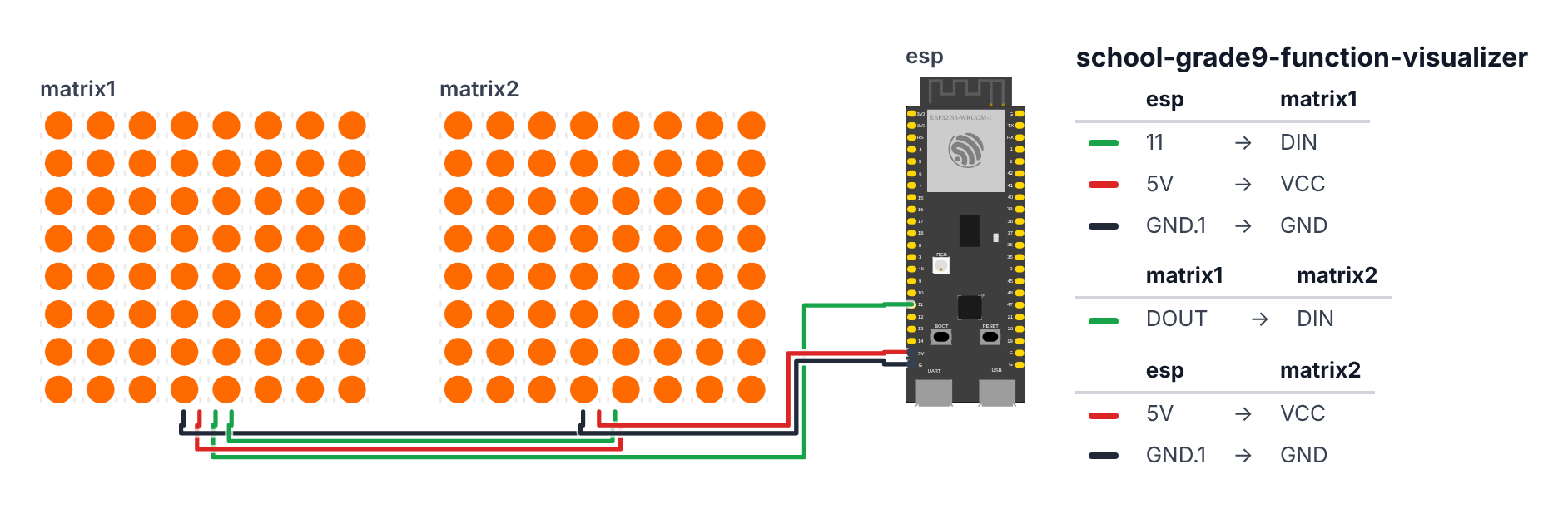
Two MAX7219 matrices are daisy-chained — the first one’s DOUT connects to the second one’s DIN.
ESP32 → First Matrix:
- DIN → GPIO 11 (C6: GPIO 22)
- CLK → GPIO 12 (C6: GPIO 23)
- CS → GPIO 10 (C6: GPIO 18)
- VCC → 5V
- GND → GND
First Matrix → Second Matrix: 6. First DOUT → Second DIN 7. Second CLK → same CLK wire (GPIO 12, C6: GPIO 23) 8. Second CS → same CS wire (GPIO 10, C6: GPIO 18) 9. Second VCC → 5V 10. Second GND → GND
Good to know: The simulator has no MAX7219 part, so the wiring picture uses a plain LED matrix that only has DIN, VCC and GND. Wire CLK and CS as listed above anyway — the real module needs them.
Check: The two matrices should be physically side-by-side so they form a 16-wide display. First matrix = left half (x 0–7), second = right half (x 8–15).
Step 2: Flash the code
Time: ~20 minutes
Install these libraries in Arduino IDE Library Manager:
- MD_MAX72XX (by MajicDesigns)
- UniversalTelegramBot (by Brian Lough)
- ArduinoJson (by Benoit Blanchon)
The big picture first. This program is a live graphing calculator made of LEDs:
- The ESP32 does math: for every x position on the display, it calculates y = mx + b and lights up the LED at that position.
- Telegram is used as a remote control: you text “m=2 b=1” and the ESP32 redraws the line instantly.
- The display is a 16×8 grid — 16 columns (x) and 8 rows (y).
A program is like a recipe. The computer reads it top to bottom and does exactly what is written, nothing more. Copy this entire recipe into Arduino IDE and upload it:
// ========== CHOOSE YOUR BOARD ==========
// Uncomment the line for YOUR board:
#define BOARD_S3    // ESP32-S3-DevKitC-1
//#define BOARD_C6  // ESP32-C6-DevKitC-1
// ========================================

#ifdef BOARD_S3
  #define PIN_CS    10
  #define PIN_MOSI  11
  #define PIN_CLK   12
#endif
#ifdef BOARD_C6
  #define PIN_CS    18
  #define PIN_MOSI  22
  #define PIN_CLK   23
#endif

#include <WiFi.h>
#include <MD_MAX72xx.h>
#include <SPI.h>
#include <UniversalTelegramBot.h>
#include <ArduinoJson.h>
#include <WiFiClientSecure.h>

#define HARDWARE_TYPE MD_MAX72XX::FC16_HW
#define MAX_DEVICES 2

const char* ssid = "YOUR_WIFI_NAME";
const char* password = "YOUR_WIFI_PASSWORD";
const char* BOT_TOKEN = "YOUR_TELEGRAM_BOT_TOKEN";

MD_MAX72XX mx = MD_MAX72XX(HARDWARE_TYPE, PIN_MOSI, PIN_CLK, PIN_CS, MAX_DEVICES);
WiFiClientSecure client;
UniversalTelegramBot bot(BOT_TOKEN, client);

float slope = 1.0;
float intercept = 0.0;

void drawFunction() {
  mx.clear();

  for (int x = 0; x < 16; x++) {
    float y = slope * (x - 8) + intercept;
    int row = 4 + (int)round(y);
    row = constrain(row, 0, 7);

    int col = x;
    mx.setPoint(row, col, true);
  }

  for (int x = 0; x < 16; x++) {
    float y = slope * (x - 8) + intercept;
    int row = 4 + (int)round(y);
    if (row != 4) mx.setPoint(4, x, true);
  }

  mx.update();
}

unsigned long lastBotCheck = 0;

void setup() {
  Serial.begin(115200);
  mx.begin();
  mx.control(MD_MAX72XX::INTENSITY, 4);
  mx.clear();

  WiFi.begin(ssid, password);
  while (WiFi.status() != WL_CONNECTED) {
    delay(500);
    Serial.print(".");
  }
  Serial.println("\nConnected!");

  client.setInsecure();

  drawFunction();
  Serial.println("Ready! Send 'm=2 b=1' in Telegram to change the function.");
}

void loop() {
  if (millis() - lastBotCheck > 2000) {
    lastBotCheck = millis();
    int numNewMessages = bot.getUpdates(bot.last_message_received + 1);

    for (int i = 0; i < numNewMessages; i++) {
      String msg = bot.messages[i].text;
      String chatId = bot.messages[i].chat_id;

      int mIdx = msg.indexOf("m=");
      int bIdx = msg.indexOf("b=");

      if (mIdx >= 0) {
        slope = msg.substring(mIdx + 2).toFloat();
      }
      if (bIdx >= 0) {
        intercept = msg.substring(bIdx + 2).toFloat();
      }

      drawFunction();

      String reply = "y = " + String(slope, 1) + "x + " + String(intercept, 1);
      reply += "\nSlope: " + String(slope, 1);
      reply += "\nIntercept: " + String(intercept, 1);
      bot.sendMessage(chatId, reply, "");
    }
  }
}
Line-by-line: what every line does and why
Lines 1–6: Borrowing ready-made instruction books
#include <WiFi.h>
#include <MD_MAX72xx.h>
#include <SPI.h>
#include <UniversalTelegramBot.h>
#include <ArduinoJson.h>
#include <WiFiClientSecure.h>
#include means “grab this instruction book.” Each library handles a big job so we do not have to write it from scratch:
- WiFi — connects the ESP32 to your home network.
- MD_MAX72xx — controls the LED matrix chips.
- SPI — the communication protocol the LED matrix uses (faster than I2C).
- UniversalTelegramBot — handles all the Telegram messaging.
- ArduinoJson — reads the JSON-formatted replies from Telegram’s servers.
- WiFiClientSecure — makes secure (HTTPS) connections to Telegram.
Lines 8–12: Giving numbers easy names
#define PIN_CS    10
#define PIN_MOSI  11
#define PIN_CLK   12

#define HARDWARE_TYPE MD_MAX72XX::FC16_HW
#define MAX_DEVICES 2
#define is a sticky note. FC16_HW is the specific hardware type of our LED matrix modules — the library needs to know the exact wiring layout inside. MAX_DEVICES 2 means two modules are daisy-chained. The three PIN names tell the ESP32 which legs connect to the matrix: CS (chip select, leg 10), MOSI (data stream, leg 11), CLK (clock beat, leg 12). On the C6 they are legs 18, 22 and 23.
Lines 14–16: Your login credentials
const char* ssid = "YOUR_WIFI_NAME";
const char* password = "YOUR_WIFI_PASSWORD";
const char* BOT_TOKEN = "YOUR_TELEGRAM_BOT_TOKEN";
const char* is a text box that never changes. You must replace these three values with your own. ssid is your WiFi name, password is the WiFi password, and BOT_TOKEN is the secret key Telegram gives you for your bot.
Lines 18–21: Creating the matrix and Telegram objects
MD_MAX72XX mx = MD_MAX72XX(HARDWARE_TYPE, PIN_MOSI, PIN_CLK, PIN_CS, MAX_DEVICES);
WiFiClientSecure client;
UniversalTelegramBot bot(BOT_TOKEN, client);
mx is the LED matrix — named so we can command it later. client is a secure internet connection. bot is our Telegram assistant — it uses the token to talk to Telegram’s servers and the client to do it securely.
Lines 23–24: Variables for m and b
float slope = 1.0;
float intercept = 0.0;
float means a number with a decimal point. slope stores the current m value. intercept stores the current b value. They start at 1 and 0 — which draws a 45° diagonal line (y = x).
Lines 26–48: drawFunction() — the heart of the project
void drawFunction() {
  mx.clear();
mx.clear() wipes all 128 LEDs dark — like erasing a whiteboard before drawing a new line.
  for (int x = 0; x < 16; x++) {
    float y = slope * (x - 8) + intercept;
    int row = 4 + (int)round(y);
    row = constrain(row, 0, 7);
    mx.setPoint(row, col, true);
  }
This for loop runs 16 times — once for each column. For each x value it:
- Calculates y using y = m(x−8) + b. The
x - 8shifts the origin to the center of the display (column 8) instead of the left edge. - Converts y into a pixel row:
row = 4 + y. Row 4 is the middle of the 8-row display. Positive y goes up from center (row numbers decrease), negative y goes down. constrain(row, 0, 7)clamps the row to valid screen range — like telling a number “you cannot go below 0 or above 7.”mx.setPoint(row, col, true)lights up that specific LED — row is the height, col is the column.
  for (int x = 0; x < 16; x++) {
    float y = slope * (x - 8) + intercept;
    int row = 4 + (int)round(y);
    if (row != 4) mx.setPoint(4, x, true);
  }
This second loop draws the x-axis (row 4, the center row). It only draws an axis dot if the function line is not already there — otherwise the whole center row would light up and obscure the line.
  mx.update();
}
mx.update() actually sends all the changes to the physical LEDs. Without this, nothing would appear. Think of it like pressing Print after you finish editing a document.
Lines 50–70: setup() — runs once on power-on
mx.begin();
mx.control(MD_MAX72XX::INTENSITY, 4);
mx.clear();
mx.begin() starts the LED matrix. mx.control(INTENSITY, 4) sets brightness to 4 out of 15 — medium brightness. mx.clear() starts with a blank display.
WiFi.begin(ssid, password);
while (WiFi.status() != WL_CONNECTED) {
  delay(500);
  Serial.print(".");
}
Connect to WiFi. while means “keep doing this as long as it is true.” WiFi.status() != WL_CONNECTED means “WiFi is not yet connected.” So the loop keeps waiting, printing a dot every half second, until the connection succeeds.
client.setInsecure();This tells the secure connection to skip certificate checking — a shortcut that works fine for a school project but would not be acceptable in a bank app. It is needed because storing Telegram’s security certificate on the ESP32 is complicated.
drawFunction();Draw the starting line (y = x) as soon as WiFi connects.
Lines 72–97: loop() — checks Telegram every 2 seconds
if (millis() - lastBotCheck > 2000) {
  lastBotCheck = millis();
  int numNewMessages = bot.getUpdates(bot.last_message_received + 1);
millis() is a stopwatch. millis() - lastBotCheck is how long since the last check. If more than 2000 milliseconds (2 seconds) have passed, check Telegram for new messages. bot.getUpdates(...) asks Telegram’s servers: “Any new messages since the last one I read?”
  for (int i = 0; i < numNewMessages; i++) {
    String msg = bot.messages[i].text;
    int mIdx = msg.indexOf("m=");
    int bIdx = msg.indexOf("b=");
    if (mIdx >= 0) slope = msg.substring(mIdx + 2).toFloat();
    if (bIdx >= 0) intercept = msg.substring(bIdx + 2).toFloat();
Loop through each new message. msg.indexOf("m=") searches for the text “m=” and returns its position — or -1 if not found. msg.substring(mIdx + 2) cuts the text starting right after “m=”. .toFloat() converts that text (“2.5”) to a number (2.5). This parses a message like “m=2 b=1” and extracts the two numbers.
    drawFunction();
    bot.sendMessage(chatId, reply, "");
Redraw the line with the new values. Send back a confirmation message to Telegram so you know it worked.
The whole thing in one sentence
On power-on, connect to WiFi and draw y = x on the LED matrix. Then every 2 seconds, check Telegram for new m and b values, update the variables, and redraw the line.
First thing to try: Send your bot the message m=0 b=0. The line should become completely flat (horizontal) — zero slope. Then send m=3 b=0 and watch the line become very steep. Then send m=1 b=-3 and watch the line shift down.
Check: After uploading, the matrix should show a diagonal line (y=x, slope=1, intercept=0). If it’s blank, check SPI connections. If it shows garbage, make sure you set
HARDWARE_TYPEtoFC16_HW.
Step 3: Set up Telegram bot
Time: ~5 minutes
- Open Telegram, search @BotFather
- Send
/newbot— name it “FunctionBot” or similar - BotFather gives you a long token — copy it
- Paste it into
BOT_TOKENin the code and re-upload
Test: Send your bot: m=2 b=0
The matrix should redraw with a steeper line. Bot replies: “y = 2.0x + 0.0”
Step 4: Present it!
Commands for your presentation:
| Send this | What it shows |
|---|---|
m=0 b=0 |
Flat line (zero slope — horizontal) |
m=1 b=0 |
45° diagonal |
m=3 b=0 |
Steep positive slope |
m=-1 b=0 |
Downward slope |
m=1 b=3 |
Shift up 3 units |
m=1 b=-3 |
Shift down 3 units |
Presentation tip: Walk your audience through slope changes first (keep b=0, change m from -2 to 2 in steps). Say: “Notice the line rotates around the origin as slope changes — this is why slope is called the ‘rate of change.’” Then change b to show translation: “The b value slides the whole line up or down without rotating it.”
What just happened
You implemented coordinate mapping — converting mathematical coordinates (x, y can be any real number) to physical pixels (0–15, 0–7). The map() and constrain() functions scaled the math-space to screen-space.
You also used SPI (Serial Peripheral Interface) — a fast communication protocol that controls the MAX7219. SPI uses 4 wires and can run at 10 million bits per second, which is why the display updates instantly.
Curriculum connections:
- Common Core Math 8.F.A.3: Interpret the equation y = mx + b as defining a linear function
- Common Core Math HSF.IF.C.7: Graph functions expressed symbolically and show key features
- Common Core Math HSF.BF.B.3: Identify the effect on the graph of replacing f(x) by f(x+k)
You didn’t just draw a line — you built a function machine. Input m and b, output a graph. That’s what graphing calculators do, except yours fits in a backpack and costs $28.
Level Up
Quadratic functions: Change the formula to y = a*x*x + b*x + c and you can visualize parabolas. Send a=1 b=0 c=0 to see y=x².
Two functions at once: Use different brightness levels (MAX7219 supports 16 levels) to show two functions simultaneously — visualize intersections.
Absolute value: Add a mode that graphs y = |mx + b|, showing the V-shape of absolute value functions.
Troubleshooting
| Problem | Fix |
|---|---|
| Matrix shows nothing | Check 5V power (not 3.3V). Check CS on GPIO 10 (C6: GPIO 18). Try mx.clear(); mx.setPoint(0,0,true); mx.update(); to test. |
| Only half the matrix works | Check DOUT of matrix 1 goes to DIN of matrix 2. Same CLK and CS for both. |
| Telegram bot never responds | Double-check BOT_TOKEN. WiFi must be connected (check Serial Monitor). Add Serial.println(WiFi.status()) to debug. |
| Line looks wrong/upside down | Flip the row calculation: change row = 4 + (int)round(y) to row = 4 - (int)round(y) |
| Upload fails | Hold BOOT button while clicking Upload in Arduino IDE. |