Parent info
Parts you need
Affiliate links — we may earn a small commission
Try this circuit in your browser!
Run the code, press the buttons and watch what happens — before you buy any parts. No account needed.
Open in Simulator →Your classmates measured with a ruler and protractor. You built a laser rangefinder.
Grade 8 geometry: similar triangles, Pythagorean theorem, law of cosines. Everyone measures triangles with plastic rulers and protractors, gets slightly different answers, and argues about whether the ruler was straight. Your teacher demonstrates theorems on the board and you copy them down.
Your device uses a VL53L0X laser sensor — the same technology in robot vacuum cleaners and self-driving cars — to measure distances to 1mm accuracy. The MPU6050 tilts to measure the angle you’re holding the device at. Together they let you: measure two sides and the included angle of any real-world triangle, then calculate the third side using the law of cosines. Point at a far wall, take two measurements, and have the device prove the Pythagorean theorem on a real object — not just paper.
That’s applied geometry.
What you’ll need
| Part | What it does | Price |
|---|---|---|
| ESP32-S3-DevKitC-1 | The brain — runs geometry calculations | ~$12 |
| VL53L0X laser distance sensor | Time-of-flight laser ranging, 2cm–200cm, ±1mm accuracy | ~$8 |
| MPU6050 | Measures the angle you’re holding the device | ~$5 |
| 0.96” OLED display | Shows distance, angle, and calculated geometry | ~$5 |
| Breadboard + jumper wires | Connects everything | ~$5 |
Total: ~$35 | Time: ~2 hours | Difficulty: ●●●○○
How does a laser distance sensor work? The VL53L0X is a Time-of-Flight (ToF) sensor. It fires an infrared laser pulse and measures how long it takes for the reflection to return. Light travels at 300,000 km/s, so even tiny time differences correspond to meaningful distances. At 1 meter, the light round-trip takes about 6.7 nanoseconds. The chip measures this with extreme precision. Same principle as LIDAR in self-driving cars — your device is a tiny version of that.
How it works (60 seconds)
Point the device at a surface and press the MEASURE button. The VL53L0X fires a laser pulse and returns the distance in millimeters. The MPU6050 simultaneously reads the tilt angle (how many degrees you’re holding the device above horizontal). The ESP32 stores three measurements (side a, angle B, side c) and uses the law of cosines to calculate the unknown side and angles. The OLED shows all stored measurements and the calculated result. Point at different spots on a room and verify the Pythagorean theorem holds for right angles.
Step 0: Review the math
Time: ~5 minutes
Law of cosines: For a triangle with sides a, b, c and the angle B opposite to side b:
b² = a² + c² - 2ac·cos(B)
If angle B = 90°, cos(90°) = 0, so b² = a² + c² — that’s the Pythagorean theorem! Law of cosines is the general version.
What you’ll measure: Two distances (a and c) to two different points from a fixed position, plus the angle between your measurements (B). The device calculates b.
Example experiment: Stand in the corner of a room. Measure the distance to one wall (a). Rotate 90°. Measure the distance to the adjacent wall (c). Angle B = 90°. The device calculates b = √(a² + c²). Now physically measure the diagonal of the room. Does it match? It should — within a centimeter.
Step 1: Wire it up
Time: ~15 minutes
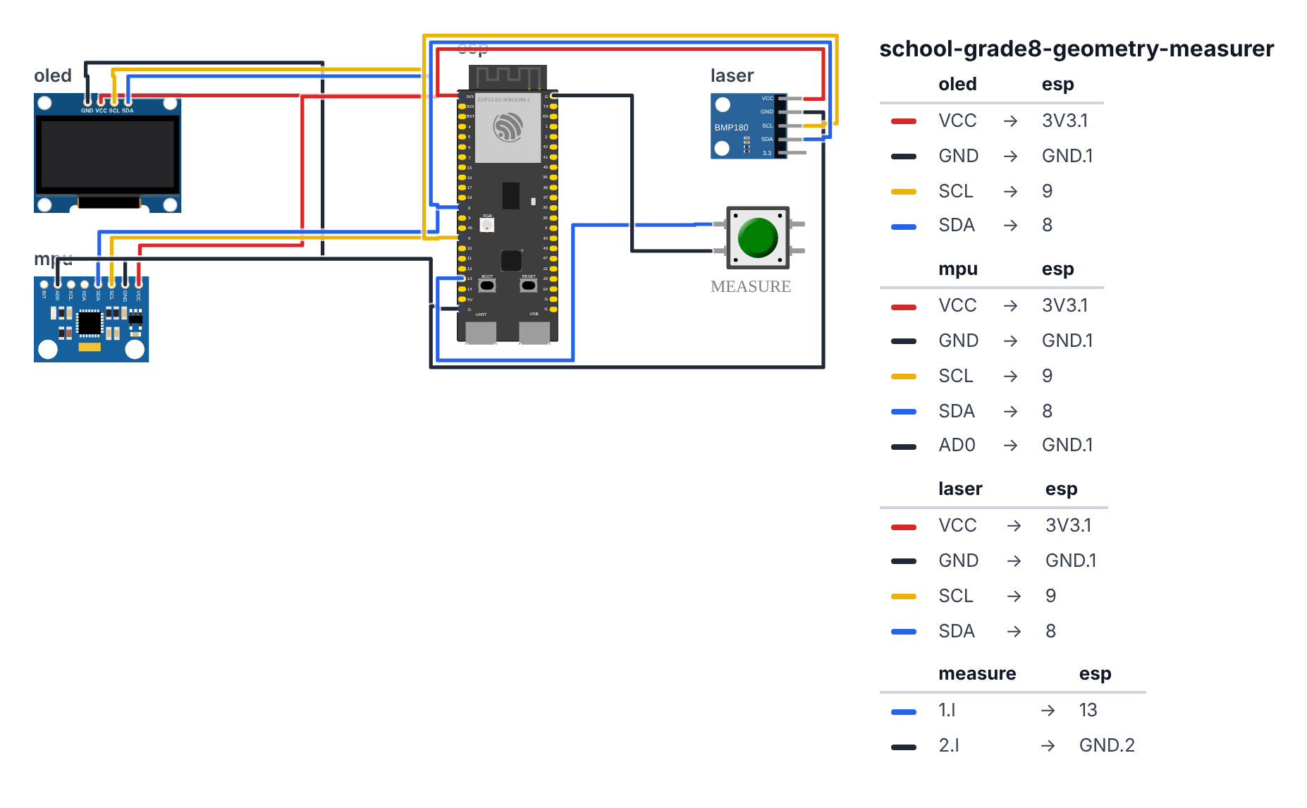
All three I2C devices share the same two data wires (SDA/SCL):
OLED Display:
- OLED VCC → board 3.3V — red wire
- OLED GND → board GND — black wire
- OLED SCL → board GPIO 9 (C6: GPIO 7) — yellow wire
- OLED SDA → board GPIO 8 (C6: GPIO 6) — blue wire
VL53L0X Laser Sensor: 5. VL53L0X VCC → board 3.3V — red wire 6. VL53L0X GND → board GND — black wire 7. VL53L0X SCL → board GPIO 9 (C6: GPIO 7) — yellow wire 8. VL53L0X SDA → board GPIO 8 (C6: GPIO 6) — blue wire
MPU6050 Accelerometer: 9. MPU6050 VCC → board 3.3V — red wire 10. MPU6050 GND → board GND — black wire 11. MPU6050 SCL → board GPIO 9 (C6: GPIO 7) — yellow wire 12. MPU6050 SDA → board GPIO 8 (C6: GPIO 6) — blue wire 13. MPU6050 AD0 → board GND — black wire
I2C addresses: OLED = 0x3C, VL53L0X = 0x29, MPU6050 = 0x68. All different — no conflicts on the shared bus.
Good to know: The simulator has no VL53L0X part, so the wiring picture uses a similar little I2C sensor board (it says BMP180, labelled “laser”) in its place. The four wires are the same.
Measure button: 14. Button one side → board GPIO 13 (C6: GPIO 5) — blue wire 15. Button other side → board GND — black wire
Step 2: Flash the code
Time: ~25 minutes
Install these libraries:
VL53L0Xby PololuMPU6050by Electronic CatsAdafruit SSD1306by AdafruitAdafruit GFX Libraryby Adafruit
Here is the big picture. This program is a handheld geometry calculator that uses real physics to measure triangles:
- The VL53L0X laser fires a pulse of infrared light and measures how long the reflection takes to return. Light travels at 300,000 km/s, so even a 1-nanosecond difference in timing means ~15cm of distance.
- The MPU6050 (accelerometer) measures gravity. Gravity always pulls straight down. By measuring how much gravity is in each axis, the chip calculates the angle you’re holding the device.
- Three button presses collect: side A (a distance), angle B (your tilt), and side C (another distance). The law of cosines then calculates the third side.
// ========== CHOOSE YOUR BOARD ==========
// Uncomment the line for YOUR board:
#define BOARD_S3    // ESP32-S3-DevKitC-1
//#define BOARD_C6  // ESP32-C6-DevKitC-1
// ========================================

#ifdef BOARD_S3
  #define PIN_SDA        8
  #define PIN_SCL        9
  #define PIN_BTN_MEAS   13
#endif
#ifdef BOARD_C6
  #define PIN_SDA        6
  #define PIN_SCL        7
  #define PIN_BTN_MEAS   5
#endif

#include <Wire.h>
#include <VL53L0X.h>
#include <MPU6050.h>
#include <Adafruit_SSD1306.h>
#include <math.h>

#define SCREEN_WIDTH 128
#define SCREEN_HEIGHT 64
Adafruit_SSD1306 display(SCREEN_WIDTH, SCREEN_HEIGHT, &Wire, -1);

VL53L0X laser;
MPU6050 imu;

#define BTN_MEASURE PIN_BTN_MEAS

float sides[3] = {0, 0, 0};
float angles[2] = {0, 0};
int measureCount = 0;

float getTiltAngle() {
  int16_t ax, ay, az, gx, gy, gz;
  imu.getMotion6(&ax, &ay, &az, &gx, &gy, &gz);

  float gxF = ax / 16384.0;
  float gyF = ay / 16384.0;
  float gzF = az / 16384.0;

  float angle = atan2(gyF, gzF) * 180.0 / PI;

  return angle;
}

float lawOfCosines(float a, float c, float angleBdeg) {
  float angleB = angleBdeg * PI / 180.0;
  float bSquared = a*a + c*c - 2*a*c*cos(angleB);
  if (bSquared < 0) return -1;
  return sqrt(bSquared);
}

float solveAngle(float a, float b, float c) {
  float cosA = (b*b + c*c - a*a) / (2*b*c);
  cosA = constrain(cosA, -1.0, 1.0);
  return acos(cosA) * 180.0 / PI;
}

void updateDisplay() {
  display.clearDisplay();
  display.setTextColor(SSD1306_WHITE);
  display.setTextSize(1);

  display.setCursor(0, 0);
  display.println("GEOMETRY MEASURER");
  display.drawLine(0, 9, 128, 9, SSD1306_WHITE);

  float tilt = getTiltAngle();
  display.setCursor(0, 12);
  display.print("Tilt: "); display.print(tilt, 1); display.println(" deg");

  display.setCursor(0, 22);
  display.print("A=");
  if (sides[0] > 0) { display.print(sides[0], 1); display.print("cm"); }
  else display.print("?");

  display.print("  B=");
  if (angles[0] > 0) { display.print(angles[0], 0); display.print("d"); }
  else display.print("?");

  display.print("  C=");
  if (sides[1] > 0) { display.print(sides[1], 1); display.print("cm"); }
  else display.print("?");

  if (sides[0] > 0 && sides[1] > 0 && angles[0] > 0) {
    float b = lawOfCosines(sides[0], sides[1], angles[0]);

    display.setCursor(0, 36);
    if (b > 0) {
      display.print("Calc b = "); display.print(b, 1); display.println(" cm");

      if (abs(angles[0] - 90.0) < 1.0) {
        float pythag = sqrt(sides[0]*sides[0] + sides[1]*sides[1]);
        display.print("Pyth: "); display.print(pythag, 1); display.println(" cm");
        display.println("RIGHT TRIANGLE!");
      }
    } else {
      display.println("Invalid triangle");
    }
  }

  display.setCursor(0, 56);
  display.print("Press BTN: ");
  switch(measureCount % 3) {
    case 0: display.println("measure side A"); break;
    case 1: display.println("measure angle B"); break;
    case 2: display.println("measure side C"); break;
  }

  display.display();
}

void takeMeasurement() {
  int step = measureCount % 3;

  if (step == 0) {
    uint16_t distMM = laser.readRangeSingleMillimeters();
    if (distMM < 8190) {
      sides[0] = distMM / 10.0;
      Serial.print("Side A: "); Serial.print(sides[0]); Serial.println(" cm");
    } else {
      Serial.println("Laser: out of range or timeout");
      return;
    }
  } else if (step == 1) {
    angles[0] = abs(getTiltAngle());
    Serial.print("Angle B: "); Serial.print(angles[0]); Serial.println(" degrees");
  } else {
    uint16_t distMM = laser.readRangeSingleMillimeters();
    if (distMM < 8190) {
      sides[1] = distMM / 10.0;
      Serial.print("Side C: "); Serial.print(sides[1]); Serial.println(" cm");

      float b = lawOfCosines(sides[0], sides[1], angles[0]);
      Serial.print("Calculated side b: "); Serial.print(b); Serial.println(" cm");

      if (b > 0) {
        float angleA = solveAngle(sides[0], b, sides[1]);
        float angleC = solveAngle(sides[1], b, sides[0]);
        float angleCheck = angleA + angles[0] + angleC;
        Serial.print("Angle A: "); Serial.println(angleA, 1);
        Serial.print("Angle B: "); Serial.println(angles[0], 1);
        Serial.print("Angle C: "); Serial.println(angleC, 1);
        Serial.print("Sum of angles (should be 180): "); Serial.println(angleCheck, 1);
      }
    } else {
      return;
    }

    Serial.print("Data: side_a="); Serial.print(sides[0]);
    Serial.print(", angle_b="); Serial.print(angles[0]);
    Serial.print(", side_c="); Serial.print(sides[1]);
  }

  measureCount++;
  updateDisplay();
}

void setup() {
  Serial.begin(115200);
  Wire.begin(PIN_SDA, PIN_SCL);

  if (!display.begin(SSD1306_SWITCHCAPVCC, 0x3C)) {
    while (true);
  }

  display.clearDisplay();
  display.setTextColor(SSD1306_WHITE);
  display.setCursor(0, 0);
  display.println("GEOMETRY MEASURER");
  display.println("Initializing...");
  display.display();

  laser.init();
  laser.setTimeout(500);
  laser.startContinuous();

  imu.initialize();
  imu.setFullScaleAccelRange(MPU6050_ACCEL_FS_2);

  pinMode(BTN_MEASURE, INPUT_PULLUP);

  Serial.println("Geometry Measurer Ready");
  Serial.println("Step 1: Point at surface, press button = side A");
  Serial.println("Step 2: Rotate to new angle, press button = angle B");
  Serial.println("Step 3: Point at surface, press button = side C");

  delay(1000);
  updateDisplay();
}

bool lastBtn = HIGH;

void loop() {
  bool btn = digitalRead(BTN_MEASURE);

  if (lastBtn == HIGH && btn == LOW) {
    delay(50);
    takeMeasurement();
  }
  lastBtn = btn;

  static unsigned long lastDisplayUpdate = 0;
  if (millis() - lastDisplayUpdate > 100) {
    updateDisplay();
    lastDisplayUpdate = millis();
  }
}
Line-by-line: what every line does and why
Lines 10–11: Creating the two sensors
VL53L0X laser;
MPU6050 imu;
laser is the time-of-flight distance sensor. imu stands for Inertial Measurement Unit — the accelerometer that measures gravity to find the tilt angle. Both share the I2C bus (pins 8/9, C6: pins 6/7).
Lines 15–17: The measurement storage
float sides[3] = {0, 0, 0};
float angles[2] = {0, 0};
int measureCount = 0;
A triangle needs: side A, angle B, side C (three measurements). sides[0] stores side A, sides[1] stores side C, sides[2] will store the calculated side B. angles[0] stores angle B. measureCount tracks how many measurements have been taken.
Lines 19–28: getTiltAngle() — reading gravity
imu.getMotion6(&ax, &ay, &az, &gx, &gy, &gz);
float gyF = ay / 16384.0;
float gzF = az / 16384.0;
float angle = atan2(gyF, gzF) * 180.0 / PI;
getMotion6 fills six variables with raw acceleration data (ax, ay, az) and gyroscope data (gx, gy, gz). Dividing by 16384.0 converts raw numbers to g-units (1.0 = 1 gravity). atan2(gyF, gzF) is the arctangent — it finds the angle between two sides of a right triangle. In this case, it finds the angle of the device relative to the direction of gravity. Multiplying by 180.0 / PI converts from radians to degrees.
Lines 30–37: lawOfCosines() — the key math
float angleB = angleBdeg * PI / 180.0;
float bSquared = a*a + c*c - 2*a*c*cos(angleB);
if (bSquared < 0) return -1;
return sqrt(bSquared);
This is the law of cosines: b² = a² + c² − 2ac·cos(B). First, convert angle B from degrees to radians (math functions use radians). Then calculate b². sqrt() gives b. If bSquared is negative, the inputs don’t form a valid triangle — return -1 as an error signal.
Lines 39–45: solveAngle() — finding all three angles
float cosA = (b*b + c*c - a*a) / (2*b*c);
cosA = constrain(cosA, -1.0, 1.0);
return acos(cosA) * 180.0 / PI;
Rearranging the law of cosines gives: cos(A) = (b² + c² − a²) / (2bc). acos() (arccosine) gives back the angle. constrain(-1.0, 1.0) prevents floating-point rounding errors from passing invalid values to acos() (which would crash). The sum of all three angles should be 180° — if it’s close to 180 in your Serial output, the measurements are accurate.
Lines 47–85: updateDisplay() — live display
The display shows: the live tilt angle (updated every 100ms so you can see it move), the stored measurements (A, B, C), and — once all three are collected — the calculated result. The switch(measureCount % 3) at the bottom shows which measurement comes next, guiding you through the three steps.
if (abs(angles[0] - 90.0) < 1.0) {
  display.println("RIGHT TRIANGLE!");
}
If the measured angle is within 1° of 90°, it’s a right triangle — and the law of cosines simplifies to the Pythagorean theorem. The device announces this live.
Lines 87–120: takeMeasurement() — the three-step sequence
int step = measureCount % 3;measureCount % 3 cycles through 0, 1, 2 (then 0 again for a new triangle). Step 0 fires the laser (side A). Step 1 reads the accelerometer (angle B). Step 2 fires the laser again (side C), then calculates side B and all angles.
uint16_t distMM = laser.readRangeSingleMillimeters();
if (distMM < 8190) { sides[0] = distMM / 10.0; }
readRangeSingleMillimeters() fires the laser and returns distance in millimeters. 8190 is the timeout/error value (the sensor returns this if nothing reflects back). Dividing by 10 converts mm to cm.
Lines 122–150: setup() — laser and IMU initialization
laser.init();
laser.setTimeout(500);
laser.startContinuous();

imu.initialize();
imu.setFullScaleAccelRange(MPU6050_ACCEL_FS_2);
laser.init() starts the VL53L0X. setTimeout(500) means “give up after 500ms if no response.” startContinuous() tells the laser to keep measuring non-stop. MPU6050_ACCEL_FS_2 sets the accelerometer range to ±2g — the most sensitive setting.
The whole thing in one sentence
Point the device, press the button three times (side, angle, side), and the law of cosines calculates the missing side — with the live tilt display showing your exact angle before each measurement.
First thing to try: Stand in a room corner. Point the laser at one wall and press the button (side A). Rotate 90° — watch the tilt display read ~90°. Press again (angle B). Point at the other wall and press (side C). The calculated side B should match the actual diagonal of the room corner.
Check: Point the device at a wall ~50cm away. Open Serial Monitor. Press the button — side A should read approximately 50. Rotate the device 90° (horizontal tilt). Press again — angle B should read approximately 90. Point at another wall. Press again — side C measured, and the law of cosines calculates side b.
Step 3: Run your geometry experiments
Experiment 1 — Verify Pythagorean theorem:
- Stand in a corner
- Measure distance to one wall (side A)
- Rotate exactly 90° (watch the live tilt angle)
- Measure distance to the other wall (side C)
- Device calculates the hypotenuse using
√(A² + C²) - Physically measure the diagonal with a tape measure
- Compare — should match within 2–3cm
Experiment 2 — Any triangle: Use a 60° angle between measurements. The law of cosines gives the third side for any triangle, not just right triangles.
Record your data: 5 different triangles (different rooms, different angles) with both the calculated and physically measured third side. How close does the math get to reality?
What just happened
Math and physics concepts:
- Law of cosines — the general form of the Pythagorean theorem, works for any triangle angle
- Time-of-flight ranging — the VL53L0X measures distance using light travel time. At the speed of light (3×10⁸ m/s), 1 meter takes 3.3 nanoseconds. The chip measures this with nanosecond precision.
- Accelerometer-based tilt measurement — gravity always pulls straight down. By measuring how much gravity is in the X, Y, and Z axes, you can calculate your orientation relative to “down.” This is how phone screens know to rotate.
- Trigonometry in the real world — law of cosines isn’t abstract. Surveyors use it to measure land. GPS satellites use similar geometry to triangulate your position.
Curriculum alignment: Common Core Math 8.G.A (Understand congruence and similarity using physical models). Also connects to HSG.SRT.D.11 (Apply the Law of Sines and the Law of Cosines to find unknown measurements in right and non-right triangles).
Presentation tip: Measure something live during your presentation. Ask: “Can you guess the diagonal distance across this classroom?” Take your two wall measurements and calculate it. Then ask someone to walk that diagonal with a tape measure. When the numbers match, the room understands why this matters.
Level Up
Area calculator: Once you have all three sides of a triangle, use Heron’s formula to calculate the area. Now you have a device that measures both the shape AND the size of real-world triangles.
Save measurements to memory: Add EEPROM storage to save your triangle measurements across power cycles. Review your geometry session later.
Multiple measurements averaged: For better accuracy, take 5 distance readings and average them instead of just one. Reduces the effect of the laser hitting a rough surface.
★★ You completed: Grade 8 Geometry Measurer!
Troubleshooting
| Problem | Fix |
|---|---|
| VL53L0X reads 8190 (error value) | Object too close (under 2cm) or too far (over 200cm), or surface absorbs infrared (black velvet). Try pointing at a white or light-colored wall. |
| MPU6050 angle is wrong or jumpy | Take multiple readings and average. Tap the device gently — accelerometers pick up vibration. Hold steady for 1 second before reading. |
| Law of cosines gives negative number under square root | The three inputs don’t form a valid triangle (triangle inequality theorem violated). Check your measurements. |
| VL53L0X not found | It uses address 0x29. Check SCL/SDA connections. It operates on 3.3V only. |
| “Sum of angles” is not 180° | Small errors add up. Floating point arithmetic and sensor noise cause 1–3° error. This is a good teaching moment about measurement uncertainty. |