Parent info
Parts you need
Affiliate links — we may earn a small commission
Try this circuit in your browser!
Run the code, press the buttons and watch what happens — before you buy any parts. No account needed.
Open in Simulator →Your classmates guessed when the bridge broke. You measured exactly.
Imagine this: Geometry class bridge competition. Everyone builds a popsicle stick bridge and stacks textbooks on it until it collapses. The winner “holds the most.” You write down an approximate number of textbooks.
Your bridge has a load cell underneath. As you add weight, an OLED display shows exactly how many grams of force the bridge is supporting. When it fails, you know: 847 grams. Failure occurred at the central joint at 12.3 seconds of peak load.
You didn’t win by luck. You engineered it.
That’s what we’re building. For about $25.
What you’ll need
| Part | What it does | Price |
|---|---|---|
| ESP32-S3-DevKitC-1 | Brain — reads the load cell and displays force | ~$12 |
| HX711 + 5kg load cell | Measures weight precisely — up to 5000 grams | ~$8 |
| OLED display 0.96” | Shows real-time load in grams | ~$4 |
| Breadboard + jumper wires | Wires everything | ~$5 |
You also need: wood scraps for the test platform, bolts or standoffs, USB power bank.
Total: ~$25 | Time: ~2–3 hours | Difficulty: ●●●○○
How it works (60 seconds)
A load cell is a metal bar with tiny strain gauges bonded to it. When force is applied, the metal bends microscopically. The strain gauges — thin resistors that change value when stretched — detect this bend. The HX711 chip amplifies that tiny signal (millivolts) and sends it to the ESP32 as a digital number.
Think of it like a very precise bathroom scale that updates 10 times per second.
The ESP32 reads the number, converts it to grams using a calibration factor, and displays it live on the OLED. It also logs the maximum load before failure — so even if the bridge collapses instantly, you have the peak value recorded.
Step 0: Build the test platform
Time: ~45 minutes
You need a platform that holds the bridge and transmits the load to the load cell.
Simple test rig design:
- Cut two pieces of wood (6” each) to serve as bridge abutments (the ends that support the bridge)
- Place the load cell flat on the table between the abutments
- Mount a small platform (3”×3” wood square) on top of the load cell — this is where weights go
- The bridge spans across the two abutments, and when weight is placed, the platform pushes down on the load cell
Alternative (simpler): Use a kitchen scale setup — tape the load cell to a flat board and hang the bridge from a hook, adding weights.
Check: Before attaching electronics, press down on the load cell platform. You should feel slight resistance — the cell is slightly flexible. Make sure it’s supported only at the designed points, not resting flat on the table.
Step 1: Wire it up
Time: ~15 minutes
The HX711 module has two sides: Load Cell inputs and MCU outputs.
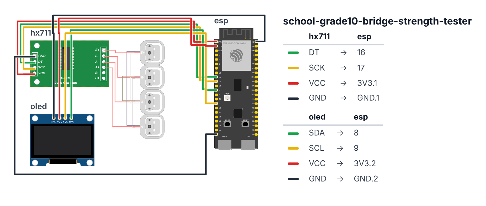
Load Cell → HX711 (usually color coded):
- Red wire → E+
- Black wire → E-
- White wire → A+
- Green wire → A-
HX711 → ESP32:
- HX711 VCC → 3.3V
- HX711 GND → GND
- HX711 DT (data) → board GPIO 16 (C6: GPIO 4)
- HX711 SCK (clock) → board GPIO 17 (C6: GPIO 23)
OLED: 5. SDA → board GPIO 8 (C6: GPIO 6) 6. SCL → board GPIO 9 (C6: GPIO 7) 7. VCC → 3.3V 8. GND → GND
Check: The load cell has 4 wires, the HX711 has 4 screw terminals on one side. Match wire colors to markings. If your colors don’t match, the HX711 typically accepts E+/E- and A+/A- — swap A+ and A- if readings are negative.
Step 2: Flash the code
Time: ~15 minutes
Install: HX711 Arduino Library (by bogde), Adafruit SSD1306, Adafruit GFX Library
The big picture first. This program is a precision digital scale that logs the maximum load before failure:
- The load cell is a metal bar with microscopic strain gauges glued to it. When force bends the bar, the gauges stretch slightly and change their electrical resistance.
- The HX711 chip amplifies that tiny resistance change into a number the ESP32 can read.
- The OLED display shows the live weight in grams, the maximum reached so far, and a progress bar from 0 to 5,000 g.
- Pressing the BOOT button tares the scale (zeros it) so you can test multiple bridge designs without changing the code.
A program is like a recipe. The computer reads it top to bottom and does exactly what is written, nothing more. Copy this entire recipe into Arduino IDE and upload it:
// ========== CHOOSE YOUR BOARD ==========
// Uncomment the line for YOUR board:
#define BOARD_S3    // ESP32-S3-DevKitC-1
//#define BOARD_C6  // ESP32-C6-DevKitC-1
// ========================================

#ifdef BOARD_S3
  #define PIN_HX_DT            16
  #define PIN_HX_SCK           17
  #define PIN_SDA              8
  #define PIN_SCL              9
  #define PIN_BUTTON           0
#endif
#ifdef BOARD_C6
  #define PIN_HX_DT            4
  #define PIN_HX_SCK           23
  #define PIN_SDA              6
  #define PIN_SCL              7
  #define PIN_BUTTON           9
#endif

#include <HX711.h>
#include <Wire.h>
#include <Adafruit_GFX.h>
#include <Adafruit_SSD1306.h>

HX711 scale;
Adafruit_SSD1306 display(128, 64, &Wire, -1);

float calibrationFactor = -7050.0;

float maxLoad = 0;
float currentLoad = 0;
unsigned long peakTime = 0;
bool testActive = false;
unsigned long testStart = 0;

float loadLog[300];
int logCount = 0;

void setup() {
  Serial.begin(115200);
  Wire.begin(PIN_SDA, PIN_SCL);

  scale.begin(PIN_HX_DT, PIN_HX_SCK);
  scale.set_scale(calibrationFactor);
  scale.tare();

  display.begin(SSD1306_SWITCHCAPVCC, 0x3C);
  display.clearDisplay();
  display.setTextColor(SSD1306_WHITE);

  display.setTextSize(1);
  display.setCursor(10, 25);
  display.println("Bridge Strength Tester");
  display.setCursor(20, 40);
  display.println("Remove all weight");
  display.setCursor(20, 52);
  display.println("then press BOOT btn");
  display.display();

  pinMode(PIN_BUTTON, INPUT_PULLUP);
  Serial.println("Press BOOT button to tare (zero) the scale");
}

void loop() {
  if (digitalRead(PIN_BUTTON) == LOW) {
    scale.tare();
    maxLoad = 0;
    logCount = 0;
    testActive = true;
    testStart = millis();
    delay(200);
    Serial.println("Tared! Start loading the bridge.");
  }

  if (scale.is_ready()) {
    currentLoad = scale.get_units(3);
    if (currentLoad < 0) currentLoad = 0;

    if (currentLoad > maxLoad) {
      maxLoad = currentLoad;
      peakTime = millis();
    }

    if (testActive && logCount < 300) {
      loadLog[logCount++] = currentLoad;
    }

    Serial.println(String(millis()) + "," + String(currentLoad, 1));

    display.clearDisplay();

    display.setTextSize(2);
    display.setCursor(0, 0);
    display.println(String((int)currentLoad) + "g");

    display.setTextSize(1);
    display.setCursor(0, 28);
    display.println("MAX: " + String((int)maxLoad) + "g");

    int barWidth = map(min((int)currentLoad, 5000), 0, 5000, 0, 128);
    display.drawRect(0, 40, 128, 10, SSD1306_WHITE);
    display.fillRect(0, 40, barWidth, 10, SSD1306_WHITE);

    display.setCursor(0, 54);
    if (currentLoad > 4000) display.println("!! NEAR LIMIT !!");
    else if (currentLoad > 2000) display.println("Heavy load");
    else if (currentLoad > 500) display.println("Moderate");
    else display.println("Press BOOT to zero");

    display.display();
  }

  delay(100);
}
Line-by-line: what every line does and why
Lines 1–4: Borrowing ready-made instruction books
#include <HX711.h>
#include <Wire.h>
#include <Adafruit_GFX.h>
#include <Adafruit_SSD1306.h>
#include means “grab this instruction book.” HX711 handles all the math of reading the tiny strain-gauge signal and converting it to grams. Wire is the I2C bus for the display. Adafruit_GFX and Adafruit_SSD1306 handle drawing on the OLED.
Lines 6–7: Pin names
#define PIN_HX_DT            16
#define PIN_HX_SCK           17
The HX711 uses two wires to talk to the ESP32: DT (data) on leg 16 and SCK (clock) on leg 17 (C6: legs 4 and 23). The clock wire ticks like a metronome to keep both chips synchronized.
Lines 9–10: Creating the objects
HX711 scale;
Adafruit_SSD1306 display(128, 64, &Wire, -1);
scale is the load cell system. display is the OLED (128 × 64 pixels, talks through Wire, no reset pin).
Lines 12–19: Variables for tracking the test
float calibrationFactor = -7050.0;
float maxLoad = 0;
float currentLoad = 0;
unsigned long peakTime = 0;
bool testActive = false;
unsigned long testStart = 0;
float loadLog[300];
int logCount = 0;
calibrationFactor is the magic number that converts the raw HX711 output to real grams — you will tune this in Step 3. It is negative because this particular wiring makes the numbers come out negative; the code fixes that automatically. maxLoad remembers the biggest force recorded so far. loadLog[300] is a shelf with 300 compartments — 30 seconds of data at 10 readings per second. bool testActive is a true/false flag that says whether a test is currently running.
Lines 21–44: setup() — morning routine
scale.begin(PIN_HX_DT, PIN_HX_SCK);
scale.set_scale(calibrationFactor);
scale.tare();
Start the scale on legs 16 and 17 (C6: legs 4 and 23). Set the conversion factor. tare() zeroes the scale — like pressing “Zero” on a kitchen scale before placing a bowl. Whatever weight is on the load cell at this moment becomes the new zero.
display.begin(SSD1306_SWITCHCAPVCC, 0x3C);
display.clearDisplay();
display.setTextColor(SSD1306_WHITE);
Start the OLED at I2C address 0x3C. Clear any leftover pixels. Set text color to white.
display.println("Bridge Strength Tester");
display.println("Remove all weight");
display.println("then press BOOT btn");
display.display();
Show setup instructions. Remove all weight first — then press BOOT to zero the scale to exactly 0g.
pinMode(PIN_BUTTON, INPUT_PULLUP);pinMode(PIN_BUTTON, INPUT_PULLUP) sets leg 0 (C6: leg 9), the BOOT button on ESP32 boards, as an input with an internal pull-up resistor. A pull-up resistor means the pin reads HIGH normally, and LOW only when the button is pressed — this is the standard way to wire buttons without extra components.
Lines 46–90: loop() — runs forever
if (digitalRead(PIN_BUTTON) == LOW) {
  scale.tare();
  maxLoad = 0;
  logCount = 0;
  testActive = true;
  testStart = millis();
  delay(200);
}
digitalRead(PIN_BUTTON) == LOW detects a button press. When the BOOT button is pressed, tare the scale again (reset to zero), clear the max load record, clear the log, and mark the test as active. delay(200) prevents the button from registering multiple times from one press.
if (scale.is_ready()) {
  currentLoad = scale.get_units(3);
  if (currentLoad < 0) currentLoad = 0;
scale.is_ready() returns true when the HX711 has a new reading available. get_units(3) averages 3 readings to reduce noise — like checking the temperature 3 times and taking the average. If the result is negative (no weight or slight noise below zero), clamp it to 0.
  if (currentLoad > maxLoad) {
    maxLoad = currentLoad;
    peakTime = millis();
  }
Track the peak load. Every time the current reading exceeds the stored maximum, update the maximum. This means when the bridge fails and weight drops suddenly, maxLoad already holds the highest value it ever reached.
  if (testActive && logCount < 300) {
    loadLog[logCount++] = currentLoad;
  }
If a test is running and there is still space in the log array (less than 300 entries), save the current reading. logCount++ writes to the current slot then advances the counter.
Serial.println(String(millis()) + "," + String(currentLoad, 1));Print a CSV line to the computer: timestamp in milliseconds, then current load in grams with 1 decimal place. You can copy all these lines from Serial Monitor into Google Sheets and plot them.
  display.setTextSize(2);
  display.println(String((int)currentLoad) + "g");
  display.setTextSize(1);
  display.println("MAX: " + String((int)maxLoad) + "g");
Show the live load in big text (size 2), max load below in small text. (int)currentLoad drops the decimal — “342g” is cleaner than “342.3g” for a live display.
  int barWidth = map(min((int)currentLoad, 5000), 0, 5000, 0, 128);
  display.drawRect(0, 40, 128, 10, SSD1306_WHITE);
  display.fillRect(0, 40, barWidth, 10, SSD1306_WHITE);
The progress bar: min((int)currentLoad, 5000) caps the input so the bar never exceeds the display. map(...) converts the 0–5000g range to 0–128 pixels. drawRect draws an empty rectangle (the outline). fillRect fills it proportionally — like a battery indicator.
if (currentLoad > 4000) display.println("!! NEAR LIMIT !!");Show a warning when approaching the load cell’s 5kg limit.
The whole thing in one sentence
On power-on, zero the scale and wait for the BOOT button. Then forever, read the force every 100 milliseconds, track the maximum, log everything to Serial and the display, and show a progress bar so you can watch the load climb in real time.
First thing to try: Press BOOT to zero the scale, then gently push down on the load cell platform with your hand. The gram reading should increase. If it goes negative instead, swap the A+ and A- wires on the HX711. If the number is very wrong (shows 10x or 0.1x the real weight), adjust calibrationFactor in Step 3.
Step 3: Calibrate your scale
Time: ~10 minutes
The calibration factor (-7050) is an estimate. To get accurate readings:
- Upload the code
- Remove all weight and press BOOT button (tares to zero)
- Place a known weight on the platform — 500g is ideal (use a bag of sugar, weigh on kitchen scale first)
- Open Serial Monitor
- Adjust
calibrationFactorup or down until the reading matches your known weight- If reading too high → increase calibrationFactor absolute value
- If reading too low → decrease it
- Re-upload with corrected value
Pro tip: Test with 100g, 500g, and 1000g weights to confirm linearity. The HX711 is accurate to ±0.1% — much better than stacked textbooks.
Step 4: Test your bridge!
Protocol:
- Build 3 bridge designs (different truss patterns, joint types, or materials)
- Zero the scale with the bridge in place
- Add weight gradually in 100g increments
- Record the maximum load at failure for each design
- Note where failure occurs (center, joints, abutments)
For your report: Calculate efficiency ratio = weight held / weight of bridge. A bridge that holds 2000g but weighs 50g has a 40:1 ratio. Compare your three designs.
Presentation tip: Bring all three bridges and test them live. Put the load cell platform on the demo table. As you add weights, the audience sees the OLED counting up in real time. When the bridge snaps — they all saw the number. “Design A: 680g. Design B: 1,240g. Design C: 1,870g — the arch distributes load across more contact points, reducing stress concentration.”
What just happened
You used strain gauge technology — the same technology in airplane wings, skyscraper foundations, and medical devices. A Wheatstone bridge circuit (four resistors arranged in a diamond) makes tiny resistance changes measurable by comparing voltages across the bridge.
Stress vs. strain: Stress is force per area (pressure). Strain is deformation per original length (how much it stretches). They’re proportional up to the elastic limit — this is Hooke’s Law applied to structures.
Curriculum connections:
- Common Core Math G-MG.3: Apply geometric methods to solve design problems
- NGSS HS-ETS1-2: Design a solution to a complex real-world problem by breaking it down into smaller, more manageable problems
- NGSS HS-ETS1-3: Evaluate a solution to a complex real-world problem based on prioritized criteria
The truss bridge geometry you studied in Geometry class directly determines which members are in tension (being pulled apart) vs. compression (being squeezed). The load cell tells you the total — the geometry determines how it’s distributed.
Level Up
Graph stress over time: Export Serial data to Google Sheets. Plot load (Y) vs. time (X) for each trial. You’ll see elastic deformation (load builds, bridge holds), then sudden failure.
Compare materials: Same bridge design in popsicle sticks, balsa wood, cardboard. Which has better strength-to-weight ratio?
Design optimization: Use math — calculate the theoretical maximum load based on beam cross-section and material yield strength. Compare to your measured value.
Troubleshooting
| Problem | Fix |
|---|---|
| Scale reads negative | Swap the A+ and A- wires on the HX711. Or multiply calibrationFactor by -1. |
| Reading jumps around too much | Increase averaging: change get_units(3) to get_units(10). |
| OLED doesn’t show anything | Check SDA=GPIO 8, SCL=GPIO 9 (C6: SDA=GPIO 6, SCL=GPIO 7), VCC=3.3V. Try address 0x3D. |
| Reads very wrong weight | Recalibrate with a known weight — see Step 3. |
| Upload fails | Hold BOOT button while clicking Upload in Arduino IDE. |