Parent info
Parts you need
Affiliate links — we may earn a small commission
Try this circuit in your browser!
Run the code, press the buttons and watch what happens — before you buy any parts. No account needed.
Open in Simulator →Your classmates painted art that stands still. Yours dances.
Imagine this: Art class final project. Everyone mounts their best painting or drawing. Impressive work, framed nicely, displayed on the wall.
Then there’s yours. A geometric frame mounted on the wall, with a ring of 60 LEDs around the border. When music plays, the LEDs pulse and ripple in sync with the beat. When it’s quiet, they glow soft and slow. When someone claps, they flash.
You didn’t just make art about sound. You made sound visible.
That’s what we’re building. For about $28.
What you’ll need
| Part | What it does | Price |
|---|---|---|
| ESP32-S3-DevKitC-1 | Brain — reads sound level, drives LED effects | ~$12 |
| WS2812B LED strip (60 LEDs) | The visual output of the art piece | ~$8 |
| MAX9814 microphone amplifier | Picks up sound amplitude — auto gain controlled | ~$5 |
| Breadboard + jumper wires | Wires it all | ~$5 |
You also need: foam board or canvas frame (12”×12” or larger), hot glue, black paint for the background.
Total: ~$28 | Time: ~2 hours | Difficulty: ●●●○○
How it works (60 seconds)
The MAX9814 microphone picks up sound and converts it to a voltage — louder sounds = higher voltage. The ESP32 reads this voltage 100 times per second and maps it to LED brightness and effects.
The math behind it: the LED brightness at any moment is proportional to the sound amplitude. When the bass hits in music, the analog pin jumps — more LEDs light up brighter. In silence, they fade to a gentle idle pattern.
This is the same technology in VU meters (those bouncing bars on old stereos) and music visualizers in media players. Yours is physical.
Step 0: Design your art piece
Time: ~30 minutes
The art direction is YOURS — the ESP32 is just the medium. Here are three design directions:
Option A: Frame — Take a 12”×16” canvas. Paint it black or dark. Mount the LED strip around the inside border. The strip is the frame, and it reacts to the room’s sound.
Option B: Geometric pattern — Cut geometric shapes from black foam board. Mount LEDs along the edges of the shapes — triangles, hexagons, concentric circles. Different sections respond differently to different frequencies.
Option C: Abstract sculpture — Weave the LED strip through a transparent acrylic or wire mesh structure. Sound causes the whole structure to glow and pulse.
Your art statement: Prepare a 2-sentence artist statement explaining what your piece means. Example: “Sound is normally invisible — we hear it but can’t see it. This piece makes the acoustic environment of a space visible as light, letting viewers see the room’s sonic texture in real time.”
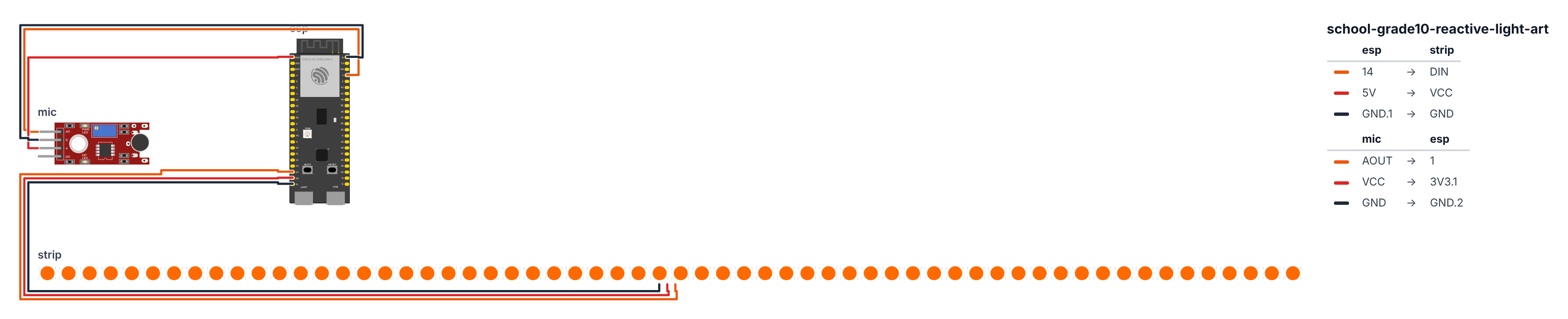
Step 1: Wire it up
Time: ~10 minutes
LED strip:
- DIN → board GPIO 14 (C6: GPIO 8)
- VCC → 5V
- GND → GND
MAX9814 microphone: 4. OUT → board GPIO 1 (C6: GPIO 4) (ADC pin) 5. VDD → 3.3V 6. GND → GND 7. GAIN pin: leave disconnected (default 40dB gain)
Check: Five wires for the microphone, three for LEDs. The MAX9814 OUT pin must go to an ADC-capable pin — GPIO 1 works (C6: GPIO 4). On the ESP32-S3, only GPIO 1–10 are safe ADC pins.
Step 2: Flash the code
Time: ~20 minutes
Install: FastLED library
The big picture first. This program converts sound into color and light:
- The MAX9814 microphone picks up sound 100 times per second and outputs a voltage. Louder sounds = bigger voltage swings.
readSoundLevel()measures the difference between the loudest and quietest sample in a 50ms window — this is called peak-to-peak amplitude, and it correlates with perceived loudness.- The smoothed level drives one of four visual modes. The program auto-cycles through the modes every 30 seconds.
A program is like a recipe. The computer reads it top to bottom and does exactly what is written, nothing more. Copy this entire recipe into Arduino IDE and upload it:
// ========== CHOOSE YOUR BOARD ==========
// Uncomment the line for YOUR board:
#define BOARD_S3    // ESP32-S3-DevKitC-1
//#define BOARD_C6  // ESP32-C6-DevKitC-1
// ========================================

#ifdef BOARD_S3
  #define PIN_NEOPIXEL  14
  #define PIN_MIC       1
#endif
#ifdef BOARD_C6
  #define PIN_NEOPIXEL  8
  #define PIN_MIC       4
#endif

#include <FastLED.h>

#define LED_PIN     PIN_NEOPIXEL
#define NUM_LEDS    60
#define MIC_PIN     PIN_MIC

CRGB leds[NUM_LEDS];

const int SAMPLE_WINDOW = 50;
int soundLevel = 0;
int peakLevel = 0;
unsigned long peakDecay = 0;

int currentMode = 0;
unsigned long lastModeChange = 0;

int smoothSound = 0;

int readSoundLevel() {
  unsigned long startTime = millis();
  int maxVal = 0, minVal = 4095;

  while (millis() - startTime < SAMPLE_WINDOW) {
    int val = analogRead(MIC_PIN);
    if (val > maxVal) maxVal = val;
    if (val < minVal) minVal = val;
  }

  return maxVal - minVal;
}

void modePulse(int level) {
  int brightness = map(level, 0, 600, 20, 255);
  uint8_t hue = map(level, 0, 600, 160, 0);
  fill_solid(leds, NUM_LEDS, CHSV(hue, 255, brightness));
}

void modeVU(int level) {
  int numOn = map(level, 0, 800, 0, NUM_LEDS);
  fill_solid(leds, NUM_LEDS, CRGB::Black);
  for (int i = 0; i < numOn; i++) {
    if (i < NUM_LEDS * 0.6) leds[i] = CRGB(0, 200, 0);
    else if (i < NUM_LEDS * 0.8) leds[i] = CRGB(200, 200, 0);
    else leds[i] = CRGB(255, 0, 0);
  }
  for (int i = 0; i < numOn/2; i++) {
    leds[NUM_LEDS - 1 - i] = leds[i];
  }
}

int ripplePos = NUM_LEDS / 2;
void modeRipple(int level) {
  fadeToBlackBy(leds, NUM_LEDS, 30);

  if (level > 200) {
    int center = NUM_LEDS / 2;
    int rippleWidth = map(level, 200, 800, 2, 8);
    uint8_t hue = millis() / 20;

    for (int r = 0; r < rippleWidth; r++) {
      int pos1 = center + (millis() / 10) % (NUM_LEDS/2);
      int pos2 = center - (millis() / 10) % (NUM_LEDS/2);
      if (pos1 < NUM_LEDS) leds[pos1] = CHSV(hue, 255, 255);
      if (pos2 >= 0) leds[pos2] = CHSV(hue + 128, 255, 255);
    }
  }
}

void modeRainbow(int level) {
  static uint8_t hueOffset = 0;
  hueOffset += map(level, 0, 800, 0, 5);

  for (int i = 0; i < NUM_LEDS; i++) {
    uint8_t h = hueOffset + (i * 256 / NUM_LEDS);
    uint8_t v = map(level, 0, 800, 30, 255);
    leds[i] = CHSV(h, 255, v);
  }
}

void setup() {
  Serial.begin(115200);
  FastLED.addLeds<WS2812B, LED_PIN, GRB>(leds, NUM_LEDS);
  FastLED.setBrightness(80);
  fill_solid(leds, NUM_LEDS, CRGB::Black);
  FastLED.show();

  Serial.println("Sound Reactive Art Ready");
  Serial.println("Make some noise!");
}

void loop() {
  soundLevel = readSoundLevel();

  smoothSound = (smoothSound * 7 + soundLevel * 3) / 10;

  if (millis() - lastModeChange > 30000) {
    lastModeChange = millis();
    currentMode = (currentMode + 1) % 4;
    Serial.println("Mode: " + String(currentMode));
  }

  switch (currentMode) {
    case 0: modePulse(smoothSound); break;
    case 1: modeVU(smoothSound); break;
    case 2: modeRipple(smoothSound); break;
    case 3: modeRainbow(smoothSound); break;
  }

  FastLED.show();

  if (millis() % 100 < 10) {
    Serial.println(String(millis()) + "," + String(soundLevel) + "," + String(smoothSound));
  }
}
Line-by-line: what every line does and why
Lines 1–6: Setup
#include <FastLED.h>
#define LED_PIN     PIN_NEOPIXEL
#define NUM_LEDS    60
#define MIC_PIN     PIN_MIC
CRGB leds[NUM_LEDS];
#include <FastLED.h> grabs the LED instruction book. LED_PIN is the data wire leg (PIN_NEOPIXEL: leg 14, C6: leg 8). NUM_LEDS 60 is the strip length. MIC_PIN is the microphone analog output leg (PIN_MIC: leg 1, C6: leg 4). leds[60] is the array of 60 color slots — one per LED.
Lines 8–16: Variables
const int SAMPLE_WINDOW = 50;
int soundLevel = 0;
int currentMode = 0;
unsigned long lastModeChange = 0;
int smoothSound = 0;
SAMPLE_WINDOW = 50 means we sample the microphone for 50 milliseconds per measurement. soundLevel holds the raw reading from the last measurement window. currentMode is 0, 1, 2, or 3 — which visual effect is active. lastModeChange records when the mode last switched. smoothSound is a smoothed version of soundLevel — explained below.
Lines 18–30: readSoundLevel() — sound measurement
int readSoundLevel() {
  unsigned long startTime = millis();
  int maxVal = 0, minVal = 4095;

  while (millis() - startTime < SAMPLE_WINDOW) {
    int val = analogRead(MIC_PIN);
    if (val > maxVal) maxVal = val;
    if (val < minVal) minVal = val;
  }

  return maxVal - minVal;
}
startTime = millis() marks the beginning of the sampling window. while (millis() - startTime < 50) keeps reading for 50 milliseconds. During that time, it reads the microphone as fast as possible — hundreds of readings. It tracks the highest and lowest values seen. return maxVal - minVal is the peak-to-peak amplitude — the full swing of the sound wave. In silence, max and min are nearly equal (small difference). During a loud clap, max and min are far apart (large difference). This single number represents loudness.
Lines 32–43: modePulse() — all LEDs pulse together
void modePulse(int level) {
  int brightness = map(level, 0, 600, 20, 255);
  uint8_t hue = map(level, 0, 600, 160, 0);
  fill_solid(leds, NUM_LEDS, CHSV(hue, 255, brightness));
}
map(level, 0, 600, 20, 255) converts the sound level (0–600 range) to a brightness (20–255). Quiet = dim but never totally off (minimum 20). Loud = full brightness. map(level, 0, 600, 160, 0) converts the same level to a color hue — 160 is blue, 0 is red. Loud sounds are warm colors; quiet sounds are cool colors. CHSV(hue, 255, brightness) uses the HSV color model (Hue, Saturation, Value) instead of RGB. Changing just hue cycles through the rainbow while keeping full color saturation.
Lines 45–59: modeVU() — VU meter (the bouncing bars)
void modeVU(int level) {
  int numOn = map(level, 0, 800, 0, NUM_LEDS);
  fill_solid(leds, NUM_LEDS, CRGB::Black);
  for (int i = 0; i < numOn; i++) {
    if (i < NUM_LEDS * 0.6) leds[i] = CRGB(0, 200, 0);
    else if (i < NUM_LEDS * 0.8) leds[i] = CRGB(200, 200, 0);
    else leds[i] = CRGB(255, 0, 0);
  }
  for (int i = 0; i < numOn/2; i++) {
    leds[NUM_LEDS - 1 - i] = leds[i];
  }
}
numOn is how many LEDs to light — proportional to sound level. Fill everything black first. Then light up numOn LEDs from the start of the strip with a green-yellow-red gradient (like the volume meters on old stereos). The second for loop copies LEDs from the start to the end in reverse — so the bar fills from both ends toward the middle simultaneously.
Lines 61–78: modeRipple() — sound creates expanding ripples
void modeRipple(int level) {
  fadeToBlackBy(leds, NUM_LEDS, 30);
  if (level > 200) {
    int center = NUM_LEDS / 2;
    uint8_t hue = millis() / 20;
    int pos1 = center + (millis() / 10) % (NUM_LEDS/2);
    int pos2 = center - (millis() / 10) % (NUM_LEDS/2);
    if (pos1 < NUM_LEDS) leds[pos1] = CHSV(hue, 255, 255);
    if (pos2 >= 0) leds[pos2] = CHSV(hue + 128, 255, 255);
  }
}
fadeToBlackBy(leds, NUM_LEDS, 30) dims every LED by 30/255 each frame — creating a fade trail. This runs every frame, so without any new light, LEDs slowly dim to black. millis() / 20 slowly cycles the hue over time — the ripple color slowly rotates through the rainbow. (millis() / 10) % (NUM_LEDS/2) moves outward from center at a constant speed — the % wraps it back when it hits the edge.
Lines 80–91: modeRainbow() — sound speeds up the rainbow
void modeRainbow(int level) {
  static uint8_t hueOffset = 0;
  hueOffset += map(level, 0, 800, 0, 5);
  for (int i = 0; i < NUM_LEDS; i++) {
    uint8_t h = hueOffset + (i * 256 / NUM_LEDS);
    uint8_t v = map(level, 0, 800, 30, 255);
    leds[i] = CHSV(h, 255, v);
  }
}
static uint8_t hueOffset = 0 — the static keyword means this variable keeps its value between function calls (it is not reset to 0 every time modeRainbow is called). hueOffset slowly accumulates, cycling the rainbow. When sound is loud, map(level, 0, 800, 0, 5) adds up to 5 per frame — the rainbow spins faster. In silence, it adds 0 — the rainbow freezes. i * 256 / NUM_LEDS spreads the full color wheel evenly across all 60 LEDs.
Lines 93–130: setup() and loop()
FastLED.addLeds<WS2812B, LED_PIN, GRB>(leds, NUM_LEDS);
FastLED.setBrightness(80);
fill_solid(leds, NUM_LEDS, CRGB::Black);
FastLED.show();
Initialize FastLED with the WS2812B strip. Set global brightness to 80/255. Turn all LEDs off. Push to hardware.
soundLevel = readSoundLevel();
smoothSound = (smoothSound * 7 + soundLevel * 3) / 10;
Read the raw sound level. Then apply a weighted average: the new smooth value is 70% of the old smooth value plus 30% of the new raw reading. This acts like a shock absorber — sudden loud noises cause a sharp rise, but the number does not jump violently. The math: if smoothSound was 100 and soundLevel is 500, the new smoothSound = (100×7 + 500×3) / 10 = (700 + 1500) / 10 = 220. It moved toward 500 but did not jump there instantly.
if (millis() - lastModeChange > 30000) {
  lastModeChange = millis();
  currentMode = (currentMode + 1) % 4;
}
Every 30 seconds, advance to the next mode. % 4 wraps from 3 back to 0 — so the four modes cycle continuously.
switch (currentMode) {
  case 0: modePulse(smoothSound); break;
  case 1: modeVU(smoothSound); break;
  case 2: modeRipple(smoothSound); break;
  case 3: modeRainbow(smoothSound); break;
}
FastLED.show();
switch jumps directly to the matching case — cleaner than four if/else checks. Each mode function fills the leds[] array. FastLED.show() then pushes those colors to the physical LEDs.
The whole thing in one sentence
On power-on, set up the LED strip and start dark (setup). Then forever, sample the microphone for 50ms, smooth the result, auto-cycle through four visual modes every 30 seconds, run the current mode to fill the LED array, and push it all to the hardware (loop).
First thing to try: After uploading, clap loudly next to the microphone. All 60 LEDs should flash brightly. Then whisper — they should dim almost to black. This confirms the microphone is responding before you mount the art piece.
Check: After uploading, make a loud sound (clap, speak loudly). The LEDs should react immediately. In silence, they should fade to a gentle idle animation. If nothing happens, check the microphone wiring.
Step 3: Assemble your art piece
Time: ~30 minutes
- Mount the ESP32 and breadboard on the back of your art piece (foam board backing)
- Route the LED strip around the front in your chosen design
- Position the microphone at the bottom edge, facing the room
- Secure all wires with hot glue
- Run power cable (USB-C) down the back and out to a power bank hidden below
For gallery display:
- Power with a USB battery bank (8+ hours of life)
- Set the piece at viewing height
- Turn it on 5 minutes before presentation so it’s warmed up and cycling
Step 4: Present it!
Artist statement (adapt to your project): “Sound is normally invisible — we hear it but cannot see it. This piece transforms acoustic information into visual information in real time. The LEDs are not programmed to look a certain way — they respond to what’s actually happening in the room. Every presentation of this piece is unique because every room sounds different.”
Presentation tip: During critique, ask your teacher to play music from their phone. Show how the piece responds differently to different genres — EDM vs. classical vs. spoken word. Point out: “The algorithm doesn’t know what music this is. It responds to amplitude patterns. But different music creates visually distinct patterns, which means the visual texture of the piece contains real information about the sound.”
What just happened
You performed real-time audio analysis — reading sound amplitude 1000+ times per second and mapping it to visual output. The SAMPLE_WINDOW technique finds the peak-to-peak amplitude (loudest minus quietest value in a time window), which correlates with perceived loudness.
The HSV color model (Hue, Saturation, Value) is more intuitive than RGB for art applications — changing only Hue cycles through colors while keeping saturation and brightness constant. You used hue to create smooth color cycling.
Curriculum connections:
- Common Core Arts: Creating: Conceiving and developing new artistic ideas
- NGSS Science Practice 5: Using mathematics and computational thinking
- Physics: Sound waves, amplitude, frequency
Sound-reactive visuals are used in professional VJing (video jockeying), concert lighting design, and interactive art installations. Your piece uses the same fundamental technique as a $50,000 concert lighting rig — just smaller.
Level Up
Frequency analysis: The ESP32 can perform a Fast Fourier Transform (FFT) to separate bass, mid, and treble frequencies. Different parts of your LED strip react to different frequency bands.
Color control via web: Add WiFi and a web page to change color palettes, mode, and sensitivity in real time from your phone during the gallery show.
Wireless sync: Build two pieces. Wire them to the same WiFi. Both react to sound simultaneously for a dual installation.
Troubleshooting
| Problem | Fix |
|---|---|
| LEDs don’t react to sound | Check MAX9814 OUT on GPIO 1 (C6: GPIO 4). Make sure it’s 3.3V power. Speak loudly directly at the mic. |
| LEDs react but very dimly | Increase brightness: FastLED.setBrightness(150) |
| Constant flickering (even in silence) | Noise in the signal — increase SAMPLE_WINDOW to 100ms. Or add delay(5) in readSoundLevel loop. |
| Colors look wrong | Swap GRB to RGB in FastLED.addLeds |
| Upload fails | Hold BOOT button while clicking Upload. |