Parent info
Parts you need
Affiliate links — we may earn a small commission
Try this circuit in your browser!
Run the code, press the buttons and watch what happens — before you buy any parts. No account needed.
Open in Simulator →Your classmates drew sin waves on paper. Yours moves in real time.
Imagine this: Pre-Calculus, unit circle and trig functions. Everyone draws y = sin(x) carefully on graph paper, marking key points at 0°, 90°, 180°, 270°, 360°.
Your device: two servos, one controlling horizontal position (X), one controlling vertical position (Y). A laser pointer is mounted on the Y servo. The ESP32 runs through angles 0–360° in a loop, setting each servo position mathematically. The laser traces a glowing sin wave on the wall, live, in real time.
Change the frequency? The wave compresses. Change the amplitude? It gets taller. Change to cosine? The wave shifts 90°. The wall becomes your graph paper.
That’s what we’re building. For about $25.
What you’ll need
| Part | What it does | Price |
|---|---|---|
| ESP32-S3-DevKitC-1 | Brain — calculates trig functions, drives servos | ~$12 |
| SG90 servo ×2 | One for X (horizontal sweep), one for Y (sine wave) | ~$6 |
| Laser module (red, 5mW) | Draws the curve on the wall | ~$4 |
| Breadboard + jumper wires | Wires everything | ~$5 |
You also need: a dark room or at least a wall 1–2 meters away, a way to mount the servos rigidly (cardboard mount works).
Total: ~$25 | Time: ~2–3 hours | Difficulty: ●●●○○
Safety note: Never point a laser at eyes. The 5mW red pointer used here is safe for wall projection but should always be pointed away from people. Work in a dark or dimly lit room for best visibility.
How it works (60 seconds)
A servo motor moves to an angle between 0° and 180° based on a PWM signal. We use two servos mounted at 90° to each other:
- Servo X sweeps left to right (maps to angle θ from 0–2π)
- Servo Y moves up and down (maps to sin(θ) or cos(θ))
As θ increases from 0 to 360°, Servo X sweeps from left to right. Simultaneously, Servo Y moves to the sine of that angle. The laser traces the curve.
It’s a live, physical Lissajous pattern generator. The x-position represents the input angle, the y-position represents the function output.
Step 0: Build the servo mount
Time: ~30 minutes
Materials: Stiff cardboard (cereal box), hot glue, popsicle sticks.
Assembly:
- Mount Servo X horizontally — it will sweep left-right. Glue to a cardboard base.
- Attach a small arm to Servo X’s horn pointing upward.
- Mount Servo Y at the end of that arm — this creates a “wrist” that moves the laser up and down.
- Glue the laser module to Servo Y’s horn so it points forward.
Alternative simple mount: Use a standard pan-tilt bracket kit ($3 separately) — designed exactly for camera/sensor mounting with two servos.
Check: Move both servos by hand through their full range. The laser should sweep across the wall in X when Servo X moves, and up/down in Y when Servo Y moves.
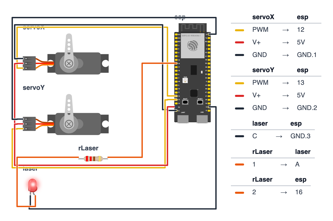
Step 1: Wire it up
Time: ~15 minutes
Servo X:
- Signal (orange) → board GPIO 12 (C6: GPIO 4)
- VCC (red) → 5V
- GND (brown) → GND
Servo Y: 4. Signal (orange) → board GPIO 13 (C6: GPIO 5) 5. VCC (red) → 5V 6. GND (brown) → GND
Laser module: 7. VCC (red) → board GPIO 16 (C6: GPIO 10) (we control it as a digital pin so we can turn it on/off) 8. GND → GND
Check: Nine wires. Both servos share 5V and GND. Laser is powered directly from a GPIO pin — at 5mW, the current draw is low enough that a GPIO pin can handle it. Test:
digitalWrite(LASER_PIN, HIGH)should turn the laser on.
Good to know: Your laser module already has a tiny resistor built in, so you don’t add one. The wiring picture shows a red LED with a 220Ω resistor in front of it — that’s just how the simulator draws the laser module.
Step 2: Flash the code
Time: ~20 minutes
Install: ESP32Servo library
The big picture first. This program turns the ESP32 into a live trigonometry machine:
- Two servo motors act like a robotic wrist — one sweeps left-right (X axis), one sweeps up-down (Y axis).
- The ESP32 steps through angles from 0 to 360°, calculates sin(angle) or cos(angle), and moves the servos to match.
- A laser pointer is mounted on the Y servo. As both servos move together, the laser traces the mathematical curve on the wall.
- A web control panel on your phone lets you change function, frequency, amplitude, and phase shift in real time.
Fill in your WiFi name and password before uploading. A program is like a recipe. Copy this entire recipe into Arduino IDE and upload it:
// ========== CHOOSE YOUR BOARD ==========
// Uncomment the line for YOUR board:
#define BOARD_S3    // ESP32-S3-DevKitC-1
//#define BOARD_C6  // ESP32-C6-DevKitC-1
// ========================================

#ifdef BOARD_S3
  #define PIN_SERVO_X  12
  #define PIN_SERVO_Y  13
  #define PIN_LASER    16
#endif
#ifdef BOARD_C6
  #define PIN_SERVO_X  4
  #define PIN_SERVO_Y  5
  #define PIN_LASER    10
#endif

#include <ESP32Servo.h>
#include <WiFi.h>
#include <WebServer.h>
#include <math.h>

Servo servoX, servoY;
#define SERVO_X_PIN PIN_SERVO_X
#define SERVO_Y_PIN PIN_SERVO_Y
#define LASER_PIN   PIN_LASER

const char* ssid = "YOUR_WIFI_NAME";
const char* password = "YOUR_WIFI_PASSWORD";
WebServer server(80);

float frequency = 1.0;
float amplitude = 1.0;
float phase = 0.0;
int   funcMode = 0;

const int SERVO_X_MIN = 30;
const int SERVO_X_MAX = 150;
const int SERVO_Y_MIN = 30;
const int SERVO_Y_MAX = 150;
const int SERVO_X_CENTER = 90;
const int SERVO_Y_CENTER = 90;
const int SERVO_RANGE = 55;

float applyFunction(float angle) {
  switch (funcMode) {
    case 0: return sin(angle + phase);
    case 1: return cos(angle + phase);
    case 2: return constrain(tan(angle + phase), -1.0, 1.0);
    case 3: return (sin(angle + phase) + cos(angle * 2)) / 2.0;
    default: return sin(angle + phase);
  }
}

void drawFunction() {
  const int STEPS = 60;

  for (int i = 0; i <= STEPS; i++) {
    float angle = (float)i / STEPS * 2.0 * PI * frequency;

    float y = applyFunction(angle) * amplitude;

    int xAngle = map(i, 0, STEPS, SERVO_X_MIN, SERVO_X_MAX);
    int yAngle = SERVO_Y_CENTER - (int)(y * SERVO_RANGE);
    yAngle = constrain(yAngle, SERVO_Y_MIN, SERVO_Y_MAX);

    servoX.write(xAngle);
    servoY.write(yAngle);

    delay(15);
  }
}

void setup() {
  Serial.begin(115200);

  servoX.attach(SERVO_X_PIN);
  servoY.attach(SERVO_Y_PIN);
  pinMode(LASER_PIN, OUTPUT);

  servoX.write(90);
  servoY.write(90);
  delay(500);

  WiFi.begin(ssid, password);
  while (WiFi.status() != WL_CONNECTED) delay(500);
  Serial.println("IP: " + WiFi.localIP().toString());

  server.on("/", []() {
    String html = "<!DOCTYPE html><html><head>";
    html += "<meta name='viewport' content='width=device-width,initial-scale=1'>";
    html += "<title>Trig Visualizer</title>";
    html += "<style>body{font-family:sans-serif;padding:20px}";
    html += "input[type=range]{width:100%}button{padding:10px 15px;margin:4px;border:none;border-radius:6px;background:#4CAF50;color:white;cursor:pointer}</style>";
    html += "<script>function set(k,v){fetch('/set?'+k+'='+v)}</script></head><body>";
    html += "<h2>Trig Visualizer</h2>";

    html += "<label>Function:</label><br>";
    html += "<button onclick=\"set('func',0)\">sin(x)</button>";
    html += "<button onclick=\"set('func',1)\">cos(x)</button>";
    html += "<button onclick=\"set('func',2)\">tan(x)</button>";
    html += "<button onclick=\"set('func',3)\">sin(x)+cos(2x)</button><br><br>";

    html += "<label>Frequency: <span id='fq'>" + String(frequency, 1) + "</span></label>";
    html += "<input type='range' min='1' max='4' step='1' value='" + String((int)frequency) + "' oninput='document.getElementById(\"fq\").innerText=this.value;set(\"freq\",this.value)'><br>";

    html += "<label>Amplitude: <span id='am'>" + String(amplitude, 1) + "</span></label>";
    html += "<input type='range' min='1' max='10' value='" + String((int)(amplitude*10)) + "' oninput='document.getElementById(\"am\").innerText=this.value/10;set(\"amp\",this.value/10)'><br>";

    html += "<label>Phase shift: <span id='ph'>" + String(phase, 2) + " rad</span></label>";
    html += "<input type='range' min='0' max='62' value='" + String((int)(phase*10)) + "' oninput='document.getElementById(\"ph\").innerText=(this.value/10).toFixed(1)+\" rad\";set(\"phase\",this.value/10)'><br><br>";

    html += "<button onclick=\"fetch('/laser/on')\" style='background:#f44336'>Laser ON</button>";
    html += "<button onclick=\"fetch('/laser/off')\" style='background:#888'>Laser OFF</button>";
    html += "</body></html>";
    server.send(200, "text/html", html);
  });

  server.on("/set", []() {
    if (server.hasArg("func"))  funcMode   = server.arg("func").toInt();
    if (server.hasArg("freq"))  frequency  = server.arg("freq").toFloat();
    if (server.hasArg("amp"))   amplitude  = server.arg("amp").toFloat();
    if (server.hasArg("phase")) phase      = server.arg("phase").toFloat();
    server.send(200, "text/plain", "ok");
  });

  server.on("/laser/on",  []() { digitalWrite(LASER_PIN, HIGH); server.send(200, "text/plain", "on"); });
  server.on("/laser/off", []() { digitalWrite(LASER_PIN, LOW);  server.send(200, "text/plain", "off"); });

  server.begin();

  digitalWrite(LASER_PIN, HIGH);
}

void loop() {
  server.handleClient();
  drawFunction();
}
Line-by-line: what every line does and why
Lines 1–4: Borrowing ready-made tools
#include <ESP32Servo.h>
#include <WiFi.h>
#include <WebServer.h>
#include <math.h>
#include means “grab this instruction book.” ESP32Servo teaches the ESP32 how to send PWM signals to servo motors. math.h provides built-in math functions like sin(), cos(), and tan(). Without it, we couldn’t calculate the wave shapes at all.
Lines 6–10: Naming the hardware
Servo servoX, servoY;
#define SERVO_X_PIN PIN_SERVO_X
#define SERVO_Y_PIN PIN_SERVO_Y
#define LASER_PIN   PIN_LASER
Servo servoX, servoY creates two servo controllers and names them. #define gives the pin numbers readable names. PIN 12 (C6: pin 4) drives the horizontal servo, pin 13 (C6: pin 5) the vertical servo, pin 16 (C6: pin 10) the laser.
Lines 16–20: Wave shape settings
float frequency = 1.0;
float amplitude = 1.0;
float phase = 0.0;
int   funcMode = 0;
These four variables control the shape of the wave. They start with default values but get updated by the web panel in real time. frequency = how many complete waves fit in the servo sweep. amplitude = how tall the wave is (1.0 = full height). phase = horizontal shift in radians. funcMode = which function (0=sin, 1=cos, 2=tan, 3=combined).
Lines 22–28: Servo limits
const int SERVO_X_MIN = 30;
const int SERVO_X_MAX = 150;
const int SERVO_Y_CENTER = 90;
const int SERVO_RANGE = 55;
Servos move from 0° to 180°, but we use only 30°–150° to avoid hitting physical stops. SERVO_Y_CENTER = 90 means the Y servo rests at the middle. SERVO_RANGE = 55 means the wave can swing 55° above or below center — the bigger this number, the taller the wave on the wall.
Lines 30–39: applyFunction() — the math engine
float applyFunction(float angle) {
  switch (funcMode) {
    case 0: return sin(angle + phase);
    case 1: return cos(angle + phase);
    case 2: return constrain(tan(angle + phase), -1.0, 1.0);
    case 3: return (sin(angle + phase) + cos(angle * 2)) / 2.0;
    default: return sin(angle + phase);
  }
}
This function takes an angle and returns a number between −1 and +1. switch is a multi-door hallway — it jumps to the right “case” based on funcMode. sin() and cos() are the built-in math functions. The + phase shifts the wave left or right. constrain(tan(...), -1.0, 1.0) clamps tan’s extreme values so the servo doesn’t try to go past its physical limits.
Lines 41–56: drawFunction() — the wave drawing loop
void drawFunction() {
  const int STEPS = 60;

  for (int i = 0; i <= STEPS; i++) {
    float angle = (float)i / STEPS * 2.0 * PI * frequency;
    float y = applyFunction(angle) * amplitude;

    int xAngle = map(i, 0, STEPS, SERVO_X_MIN, SERVO_X_MAX);
    int yAngle = SERVO_Y_CENTER - (int)(y * SERVO_RANGE);
    yAngle = constrain(yAngle, SERVO_Y_MIN, SERVO_Y_MAX);

    servoX.write(xAngle);
    servoY.write(yAngle);

    delay(15);
  }
}
The for loop runs 61 times (0 through 60). Each step:
anglegoes from 0 to 2π × frequency (one or more full cycles).applyFunction(angle)gives the Y value (−1 to +1).map(i, 0, STEPS, SERVO_X_MIN, SERVO_X_MAX)converts step number to servo degrees — like converting inches to centimeters with a ratio.SERVO_Y_CENTER - (int)(y * SERVO_RANGE)converts the −1/+1 output to servo degrees. Subtracting from the center means positive Y goes up, negative goes down.constrain()is a safety net — clips the value to the allowed range so the servo doesn’t jam.servoX.write()andservoY.write()move both servos to those angles.delay(15)pauses 15ms so the laser dot has time to visibly illuminate that spot.
Lines 58–75: setup() — the morning routine
servoX.attach(SERVO_X_PIN);
servoY.attach(SERVO_Y_PIN);
pinMode(LASER_PIN, OUTPUT);

servoX.write(90);
servoY.write(90);
delay(500);
attach() connects the servo library to the actual pin — like plugging the servo controller into the right port. write(90) moves both servos to center before starting. The 500ms delay gives the servos time to physically reach center before the laser turns on.
digitalWrite(LASER_PIN, HIGH) at the end of setup() turns the laser on — from this point, every servo movement is drawn in light.
The web control panel
server.on("/set", []() {
  if (server.hasArg("func"))  funcMode   = server.arg("func").toInt();
  if (server.hasArg("freq"))  frequency  = server.arg("freq").toFloat();
  ...
  server.send(200, "text/plain", "ok");
});
When you drag a slider on your phone, the browser sends a request like /set?freq=2. server.hasArg("freq") checks if “freq” is in the request. server.arg("freq").toFloat() extracts the number as a decimal. These four lines update the wave settings instantly — the next drawFunction() call uses the new values.
Lines 113–116: loop() — just two lines
void loop() {
  server.handleClient();
  drawFunction();
}
server.handleClient() processes any pending web requests (slider changes from your phone). Then drawFunction() immediately draws the next full wave sweep. The laser traces the curve over and over, continuously redrawing it on the wall.
The whole thing in one sentence
The ESP32 loops forever: check the phone for setting changes, then sweep both servos through one full wave — the laser traces the mathematical function on the wall, live, and updates instantly when you change any parameter from your phone.
First thing to try: upload and connect. In a dim room, the laser should trace a smooth sine wave. On your phone’s web panel, tap “cos(x)” — the wave shifts 90° to the right. That 90° shift is the entire relationship between sine and cosine, made physical.
Check: After uploading, the laser should start tracing a sine wave on the wall. The web dashboard lets you change everything from your phone.
Step 3: Tune the geometry
Time: ~15 minutes
Point the device at a wall 1–2 meters away. The further the wall, the wider and taller the trace.
Adjust servo range if the wave looks too small or goes off the wall:
const int SERVO_RANGE = 55; // Increase for taller waves, decrease for shorterCheck the X axis is sweeping fully left-to-right. Adjust SERVO_X_MIN and SERVO_X_MAX if needed.
Dark room tip: This looks dramatically better in a dark room or with a white paper on the wall as a screen.
Step 4: Present it!
Demo for presentation:
- Start with
sin(x)— one full wave - Change frequency to 2 — “the wave completes twice in the same X range. That’s frequency. In audio, 2× frequency = one octave higher.”
- Change to
cos(x)— “cosine is just sine shifted 90°. Same shape, different starting point.” - Add phase shift — “phase shift slides the whole wave left or right. You’ve seen this as the delay between two speakers.”
- Show
sin(x) + cos(2x)— “real-world wave forms are combinations of multiple frequencies. This is the beginning of Fourier analysis.”
Presentation tip: Dim the lights for maximum impact. Let the audience request changes via your phone web interface. Have them call out “make the frequency 3!” and demonstrate immediately. Controlling the mathematics in real time beats a static drawing every time.
What just happened
You implemented parametric motion — the X and Y positions are both functions of a third parameter (angle θ). This is how CNC machines, 3D printers, and robot arms work: each axis follows an independent mathematical function of time.
The servo angle conversion (map()) performs the coordinate transformation from math-space (−1 to +1) to hardware-space (30° to 150°). This is a linear function — exactly what you’re studying in Pre-Calculus.
Curriculum connections:
- Common Core Math F-TF.5: Choose trigonometric functions to model periodic phenomena with specified amplitude, frequency, and midline
- Common Core Math F-TF.2: Explain how the unit circle in the coordinate plane extends the definitions of sine and cosine
- AP Pre-Calculus: Trigonometric functions, transformations, periodicity
The phase shift you can control corresponds to f(x) = sin(x + φ) — a horizontal translation. You’re exploring the transformation of functions physically.
Level Up
Lissajous figures: Set Servo X to sin(t) and Servo Y to sin(2t + π/4). You’ll get the classic Lissajous patterns — used in oscilloscopes to compare signal frequencies.
Draw letters: Parameterize letter shapes and draw them with the laser. Draw your name on the wall by encoding each letter as a series of line segments.
Sound input: Add a microphone. Make the amplitude of the wave respond to how loud the room is. The wave grows when you speak, shrinks in silence.
Troubleshooting
| Problem | Fix |
|---|---|
| Servos jitter or hum | Use external 5V power supply instead of board’s 5V pin. Two servos can draw more current than USB provides. |
| Wave looks wrong shape | Check servo range constants. Make sure Servo X and Y are in the right positions. |
| Laser doesn’t turn on | Check GPIO 16 (C6: GPIO 10) — try digitalWrite(LASER_PIN, HIGH) in setup. |
| Web page doesn’t load | Check IP in Serial Monitor. Must be on same WiFi. |
| Upload fails | Hold BOOT button while clicking Upload. |