Parent info
Parts you need
Affiliate links — we may earn a small commission
Try this circuit in your browser!
Run the code, press the buttons and watch what happens — before you buy any parts. No account needed.
Open in Simulator →Your classmates made a potato battery and guessed it worked. You measured 0.847V.
Imagine this: Chemistry class, electrochemistry unit. Everyone builds a galvanic cell with copper and zinc electrodes in salt water. They touch the electrodes to a small LED — it glows dimly. “It works!” they say.
You connect the electrodes to your ESP32. The OLED displays: 0.847V — close to the theoretical 1.10V for Cu-Zn. Then you swap in magnesium vs. copper: 1.734V. Then try aluminum vs. zinc: 0.902V. You compare 6 metal combinations and verify the electrochemical series with real measurements.
That’s what we’re building. For about $20.
What you’ll need
| Part | What it does | Price |
|---|---|---|
| ESP32-S3-DevKitC-1 | Brain — reads voltage precisely, displays and logs | ~$12 |
| OLED display 0.96” | Shows voltage, cell identity, and comparison | ~$4 |
| Breadboard + jumper wires | Wires the voltage divider and connections | ~$5 |
You also need: 2× resistors (10kΩ), 2× resistors (20kΩ), metal electrodes (copper, zinc, aluminum, iron, magnesium strips), salt solution (NaCl in water), small beakers.
Total: ~$20 | Time: ~1–2 hours | Difficulty: ●●○○○
How it works (60 seconds)
The ESP32’s ADC reads voltages from 0 to 3.3V. A galvanic cell can produce up to 2V, which is too high for direct reading. Solution: a voltage divider — two resistors that proportionally reduce the voltage.
Using a 10kΩ and 20kΩ resistor in series: Vout = Vin × (20k / (10k + 20k)) = Vin × 0.667. A 2V input becomes 1.33V output — safe for the ESP32 ADC. We then multiply the reading by 1.5 to get back to real voltage.
The ESP32’s 12-bit ADC gives 4096 steps over 3.3V = 0.8mV resolution. Enough to see differences between metal combinations.
Step 0: Prepare your galvanic cells
Time: ~30 minutes
The electrochemical series (standard reduction potentials):
| Metal | E° (V) |
|---|---|
| Magnesium (Mg) | −2.37 |
| Aluminum (Al) | −1.66 |
| Zinc (Zn) | −0.76 |
| Iron (Fe) | −0.44 |
| Hydrogen (H) | 0.00 (reference) |
| Copper (Cu) | +0.34 |
Theoretical cell voltage = E°cathode − E°anode
Examples:
- Zn/Cu: 0.34 − (−0.76) = 1.10V (classic galvanic cell)
- Mg/Cu: 0.34 − (−2.37) = 2.71V
- Al/Cu: 0.34 − (−1.66) = 2.00V
Your measured voltages will be lower than theoretical due to internal resistance and electrode polarization.
Prepare 3 beakers with the same electrolyte (saturated NaCl solution) and clean electrode surfaces with sandpaper before each test.
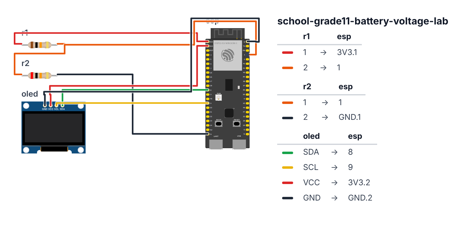
Step 1: Wire the voltage divider
Time: ~15 minutes
Voltage divider circuit:
- Galvanic cell positive → top node
- 10kΩ resistor → from top node to middle node
- 20kΩ resistor → from middle node to GND
- Middle node → board GPIO 1 (C6: GPIO 4) (ADC input)
- Galvanic cell negative → GND
This creates: V_measured = V_cell × (20k / 30k) = V_cell × 0.6667
Maximum safe input: 3.3V / 0.6667 = 4.95V max cell voltage
OLED:
- SDA → board GPIO 8 (C6: GPIO 6)
- SCL → board GPIO 9 (C6: GPIO 7)
- VCC → 3.3V
- GND → GND
Check: Before connecting a cell, check voltage at GPIO 1 (C6: GPIO 4) with a multimeter if available. It should read 0V with no cell connected. Short the cell inputs together — it should still read 0V.
Step 2: Flash the code
Time: ~15 minutes
Install: Adafruit SSD1306, Adafruit GFX Library
The big picture first. This program turns the ESP32 into a precision voltmeter for chemistry lab:
- The voltage divider (two resistors) shrinks the galvanic cell voltage to a safe size the ESP32 can read.
- The ADC (analog-to-digital converter) inside the ESP32 converts that small voltage into a number.
- The program shows the measured voltage AND the theoretical prediction side by side so you can calculate efficiency.
- The BOOT button advances through 6 different metal combinations, logging each one to a CSV.
A program is like a recipe. The computer reads it top to bottom and does exactly what’s written. Copy this entire recipe into Arduino IDE and upload it:
// ========== CHOOSE YOUR BOARD ==========
// Uncomment the line for YOUR board:
#define BOARD_S3    // ESP32-S3-DevKitC-1
//#define BOARD_C6  // ESP32-C6-DevKitC-1
// ========================================

#ifdef BOARD_S3
  #define PIN_SDA      8
  #define PIN_SCL      9
  #define PIN_VOLTAGE  1
  #define PIN_BUTTON   0
#endif
#ifdef BOARD_C6
  #define PIN_SDA      6
  #define PIN_SCL      7
  #define PIN_VOLTAGE  4
  #define PIN_BUTTON   9
#endif

#include <Wire.h>
#include <Adafruit_GFX.h>
#include <Adafruit_SSD1306.h>

Adafruit_SSD1306 display(128, 64, &Wire, -1);

#define VOLTAGE_PIN PIN_VOLTAGE

const float DIVIDER_RATIO = 0.6667;
const float VREF = 3.3;
const float ADC_MAX = 4095.0;

struct CellData {
  const char* name;
  float theoretical;
};

CellData cells[] = {
  {"Zn/Cu",    1.10},
  {"Mg/Cu",    2.71},
  {"Al/Cu",    2.00},
  {"Fe/Cu",    0.78},
  {"Zn/Fe",    0.32},
  {"Mg/Zn",    1.61}
};

int currentCell = 0;
float voltageReadings[6];
bool measured[6] = {false};

float readVoltage() {
  long sum = 0;
  for (int i = 0; i < 50; i++) {
    sum += analogRead(VOLTAGE_PIN);
    delay(2);
  }
  float adcAvg = sum / 50.0;
  float vadcPin = (adcAvg / ADC_MAX) * VREF;
  float vcell = vadcPin / DIVIDER_RATIO;
  return vcell;
}

void updateDisplay(float v) {
  display.clearDisplay();
  display.setTextSize(1);
  display.setCursor(0, 0);
  display.println("Battery Voltage Lab");

  display.setCursor(0, 12);
  display.println("Cell: " + String(cells[currentCell].name));

  display.setTextSize(2);
  display.setCursor(0, 24);
  display.println(String(v, 3) + "V");

  display.setTextSize(1);
  display.setCursor(0, 44);
  float theory = cells[currentCell].theoretical;
  float efficiency = (v / theory) * 100;
  display.println("Theory: " + String(theory, 2) + "V (" + String(efficiency, 0) + "%)");

  display.setCursor(0, 54);
  display.println("BOOT=next cell  " + String(currentCell+1) + "/6");

  display.display();
}

void setup() {
  Serial.begin(115200);
  Wire.begin(PIN_SDA, PIN_SCL);
  display.begin(SSD1306_SWITCHCAPVCC, 0x3C);

  pinMode(PIN_BUTTON, INPUT_PULLUP);

  display.clearDisplay();
  display.setTextSize(1);
  display.setCursor(5, 20);
  display.println("Galvanic Cell");
  display.setCursor(15, 32);
  display.println("Voltage Logger");
  display.display();
  delay(2000);

  Serial.println("cell,measured_V,theoretical_V,efficiency_%");
}

unsigned long lastSample = 0;

void loop() {
  if (digitalRead(PIN_BUTTON) == LOW) {
    float v = readVoltage();
    voltageReadings[currentCell] = v;
    measured[currentCell] = true;

    Serial.println(String(cells[currentCell].name) + "," +
                   String(v, 3) + "," +
                   String(cells[currentCell].theoretical, 2) + "," +
                   String((v/cells[currentCell].theoretical)*100, 1));

    currentCell = (currentCell + 1) % 6;
    delay(300);
  }

  if (millis() - lastSample > 200) {
    lastSample = millis();
    float v = readVoltage();
    updateDisplay(v);
  }
}
Line-by-line: what every line does and why
Lines 1–3: Borrowing ready-made tools
#include <Wire.h>
#include <Adafruit_GFX.h>
#include <Adafruit_SSD1306.h>
#include means “grab this instruction book.” These three books tell the ESP32 how to talk over two-wire I2C, how to draw graphics, and how to control the OLED screen. Without them, we would have to write hundreds of lines ourselves.
Line 5: Creating the display
Adafruit_SSD1306 display(128, 64, &Wire, -1);This creates the display and gives it the name display. 128 and 64 are the width and height in pixels (dots). &Wire tells it to talk through the two I2C wires. -1 means “I don’t have a reset button.”
Lines 7–10: Measurement constants
#define VOLTAGE_PIN PIN_VOLTAGE

const float DIVIDER_RATIO = 0.6667;
const float VREF = 3.3;
const float ADC_MAX = 4095.0;
#define gives PIN_VOLTAGE — leg number 1 (C6: leg 4), set in the board block at the top — the name VOLTAGE_PIN. That’s the ESP32 leg where the voltage divider connects. The three const float lines are unchangeable numbers: the divider shrinks voltage to 2/3 of the original (0.6667), the ESP32 can read up to 3.3 volts, and its ADC gives 4095 as the maximum reading. float means the number can have a decimal point.
Lines 12–21: A structure and a table of 6 cells
struct CellData {
  const char* name;
  float theoretical;
};
struct is like designing a filing card. This card has two fields: a name (like “Zn/Cu”) and a theoretical voltage number. Every metal combination gets its own card.
CellData cells[] = {
  {"Zn/Cu",    1.10},
  ...
};
cells[] is a box with 6 slots, each holding one of those filing cards. The square brackets [] tell the computer to make it exactly as long as the data inside.
Lines 23–26: Tracking which cell we’re on
int currentCell = 0;
float voltageReadings[6];
bool measured[6] = {false};
currentCell is a counter that starts at 0 (the first slot in the table). voltageReadings[6] is 6 empty boxes for storing the measured voltages. bool measured[6] is a row of 6 light switches — false means not yet measured. bool means the value is either true or false, nothing in between.
Lines 28–37: readVoltage() — measuring the battery
float readVoltage() {
  long sum = 0;
  for (int i = 0; i < 50; i++) {
    sum += analogRead(VOLTAGE_PIN);
    delay(2);
  }
  float adcAvg = sum / 50.0;
  float vadcPin = (adcAvg / ADC_MAX) * VREF;
  float vcell = vadcPin / DIVIDER_RATIO;
  return vcell;
}
This is a function — a small recipe with its own name. Instead of reading once (which can be noisy), it reads 50 times and adds them all into sum. Then sum / 50.0 gives the average — like averaging 50 ruler measurements instead of just one.
(adcAvg / ADC_MAX) * VREF converts the raw number (0–4095) into a real voltage (0–3.3V). Think of it as converting from “ADC units” to “volts” using a proportion.
vadcPin / DIVIDER_RATIO undoes the shrinking the voltage divider did. If the divider made the voltage 2/3 smaller, dividing by 0.6667 makes it 3/2 bigger again — back to the real battery voltage.
return vcell hands the answer back to whoever called this function, like a vending machine delivering what you paid for.
Lines 39–58: updateDisplay() — drawing the screen
void updateDisplay(float v) {This function receives one number, v (the measured voltage), and uses it to draw the screen. void means it gives nothing back — it just draws and is done.
Inside, display.clearDisplay() wipes the screen clean. Without this, new text piles on top of old text and becomes unreadable.
display.setTextSize(2) makes big text. display.setCursor(0, 24) moves the pen to position (0 pixels from left, 24 pixels from top). display.println(String(v, 3) + "V") writes the voltage with 3 decimal places, then adds “V”.
float efficiency = (v / theory) * 100;This calculates how close the real voltage is to the theoretical one, as a percentage. If theory says 1.10V and you measured 0.88V, efficiency = (0.88 / 1.10) × 100 = 80%.
display.display() is the most important line — nothing appears on screen until you call this. Everything before it was drawn only in memory, like ink that hasn’t been pressed onto paper yet.
Lines 60–76: setup() — runs once at power-on
void setup() {
  Serial.begin(115200);
  Wire.begin(PIN_SDA, PIN_SCL);
  display.begin(SSD1306_SWITCHCAPVCC, 0x3C);

  pinMode(PIN_BUTTON, INPUT_PULLUP);
  ...
}
setup() is the morning routine — runs once when you plug in power. Serial.begin(115200) opens the “phone line” to your computer through USB. Wire.begin(PIN_SDA, PIN_SCL) tells the ESP32 which legs (pins 8 and 9; C6: pins 6 and 7) have the I2C wires. display.begin(...) wakes up the OLED at address 0x3C — like dialing a phone number to reach the display specifically.
pinMode(PIN_BUTTON, INPUT_PULLUP) sets pin 0 (C6: pin 9), the BOOT button, as an input — meaning the ESP32 listens to it rather than controls it. INPUT_PULLUP means “treat the pin as HIGH by default; it goes LOW only when the button is pressed.”
The Serial.println("cell,measured_V...") line prints a CSV header — the column names for the spreadsheet you’ll build from this data.
Lines 80–100: loop() — repeats forever
void loop() {
  if (digitalRead(PIN_BUTTON) == LOW) {
    float v = readVoltage();
    ...
    currentCell = (currentCell + 1) % 6;
    delay(300);
  }

  if (millis() - lastSample > 200) {
    lastSample = millis();
    float v = readVoltage();
    updateDisplay(v);
  }
}
loop() beats like a heartbeat — thousands of times per second. digitalRead(PIN_BUTTON) == LOW asks “is the BOOT button pressed right now?” (== is a question, not a command — “is it equal to?”).
When pressed: measure voltage, save it, print it to the computer, then currentCell = (currentCell + 1) % 6 moves to the next cell. The % symbol means “remainder after dividing.” After cell 5, remainder of 6/6 = 0 — so it wraps back to cell 0 like a clock. delay(300) waits 300 milliseconds so one press doesn’t trigger many times.
The second if runs every 200 milliseconds (using millis() as a stopwatch) to keep the display updating live even when you’re not pressing anything.
The whole thing in one sentence
When powered on, the ESP32 wakes up the display and waits for you to connect galvanic cells. It shows the live voltage every 200ms. When you press BOOT, it saves the measurement and advances to the next cell — after all 6, copy the Serial Monitor CSV into a spreadsheet.
First thing to try: connect a fresh AA battery (1.5V) to the input. The display should read somewhere around 1.4–1.6V. If it reads 0V, check that VOLTAGE_PIN (GPIO 1, C6: GPIO 4) is wired to the middle node of your voltage divider.
Check: Without any cell connected, the display should show near 0.000V. Connect a fresh AA battery (1.5V) as a test — you should read approximately 1.5V (maybe 1.3–1.6V due to ADC nonlinearity).
Step 3: Calibrate (optional but better)
For improved accuracy, calibrate with a known voltage:
- Connect a fresh AA battery (actual voltage, measured with a $5 multimeter from the dollar store)
- Note what the ESP32 reads vs. the multimeter
- Adjust:
float vcell = vadcPin / DIVIDER_RATIO * CORRECTION_FACTOR;
Example: Multimeter says 1.52V, ESP32 reads 1.47V. Correction = 1.52/1.47 = 1.034.
Step 4: Test all 6 cells!
For each metal combination:
- Clean electrodes with sandpaper (removes oxide layer)
- Dip both electrodes in the same beaker of salt water (don’t let metals touch)
- Connect positive electrode (more noble metal) to divider input, negative to GND
- Wait 30 seconds for voltage to stabilize
- Read voltage on display
- Press BOOT to log and advance to next cell
Presentation tip: Set up all 6 cells on a tray during your presentation. Point to each one, read the voltage live, and compare to theoretical. Say: “The Zn/Cu cell produced 0.85V — 77% of the theoretical 1.10V. The losses come from internal resistance of the electrolyte and electrode polarization, which are real-world effects the textbook electrochemical series doesn’t account for.”
What just happened
You measured electromotive force (EMF) using an ADC with a voltage divider. The voltage divider is a fundamental circuit — it appears in virtually every electronic circuit as a way to scale voltages to safe levels.
The electrochemical series predicts which metal will oxidize (lose electrons) and which will reduce (gain electrons). A larger difference in reduction potentials = higher cell voltage. Your measurements verify this relationship experimentally.
Curriculum connections:
- NGSS HS-PS1-2: Construct and revise an explanation for the outcome of a simple chemical reaction based on the outermost electron states of atoms
- AP Chemistry: Electrochemistry, Nernst equation, standard reduction potentials, galvanic vs. electrolytic cells
- Common Core Math: Proportional reasoning, percentage calculations, data analysis
Real batteries (lithium-ion, lead-acid, NiMH) use the same principle — choosing electrode materials with the largest practical voltage difference that’s also chemically stable.
Level Up
Nernst equation: The theoretical voltage changes with ion concentration. Vary the NaCl concentration and measure how voltage changes. Compare to the Nernst equation prediction.
Internal resistance: Connect a variable load resistor. Measure voltage under load at different resistances. Plot voltage vs. current to find internal resistance (slope).
Lemon/potato battery: Test unconventional electrolytes — lemon juice, potato, Gatorade. Graph which produces highest voltage and lowest internal resistance.
Troubleshooting
| Problem | Fix |
|---|---|
| Reads 0V always | Check voltage divider wiring. Verify cell is actually producing voltage (try with a multimeter). |
| Reads too high (3.3V+) | Voltage divider ratio wrong — check resistor values. Cell voltage may exceed 4.95V limit. |
| Unstable reading | Clean electrode surfaces, ensure metals aren’t touching in the electrolyte. Average more samples. |
| OLED blank | SDA=GPIO 8, SCL=GPIO 9 (C6: SDA=GPIO 6, SCL=GPIO 7). Check 3.3V supply. |
| Upload fails | Hold BOOT button while clicking Upload. |