Parent info
Parts you need
Affiliate links — we may earn a small commission
Try this circuit in your browser!
Run the code, press the buttons and watch what happens — before you buy any parts. No account needed.
Open in Simulator →Your classmates timed 10 swings with a stopwatch. You measured 100 with an accelerometer.
Imagine this: Physics lab, simple pendulum. The goal is to measure g (gravitational acceleration, 9.81 m/s²). Everyone counts swings for 30 seconds and divides. Stopwatch timing, ±0.2 second error per reading. Maybe ±5% accuracy on g.
You attach an MPU-6050 accelerometer to the pendulum bob. It logs acceleration data at 100Hz. You detect every zero-crossing of the swing automatically. After 100 swings (about 5 minutes), you calculate: g = 9.79 ± 0.03 m/s². That’s 0.2% error. Textbook value is 9.81. You’re within experimental uncertainty.
That’s what we’re building. For about $22.
What you’ll need
| Part | What it does | Price |
|---|---|---|
| ESP32-S3-DevKitC-1 | Brain — reads IMU, calculates period, computes g | ~$12 |
| MPU-6050 accelerometer | Measures pendulum acceleration at 100Hz | ~$4 |
| OLED display 0.96” | Shows period, g, and measurement count live | ~$4 |
| Breadboard + jumper wires | Wires it up | ~$5 |
You also need: string or thread, small weight (50–100g), ruler or tape measure (for string length), tape.
Total: ~$22 | Time: ~2 hours | Difficulty: ●●●○○
How it works (60 seconds)
The simple pendulum formula is: T = 2π√(L/g)
Solve for g: g = 4π²L/T²
Where T is the period (time for one complete swing) and L is the string length.
The trick is measuring T accurately. A stopwatch gives you one measurement per trial. An accelerometer at 100Hz gives you 100 measurements per second — you detect the zero-crossing of the swing (when the pendulum is vertical and acceleration in the swing direction is zero) and measure the time between crossings.
Average 100+ periods to get a precise T. Measure L once with a ruler. Calculate g.
Step 0: Build the pendulum
Time: ~20 minutes
Materials:
- String: 40–60 cm long (measure EXACTLY with a ruler — this is your most important measurement)
- Weight: Tape the MPU-6050 module to a heavy washer or bolt (50g minimum)
- Mount: Tape the string to a desk edge or hang from a doorframe
Important:
- String length L = measured from the pivot point to the center of mass of the weight
- Swing amplitude should be small (less than 15°) for the simple pendulum formula to be accurate
- Keep the string from twisting — it should swing in one plane only
Check: Let the pendulum swing freely. It should swing back and forth smoothly without rotating. If it twists, the string is too light — use heavier thread or fishing line.
Step 1: Wire it up
Time: ~10 minutes
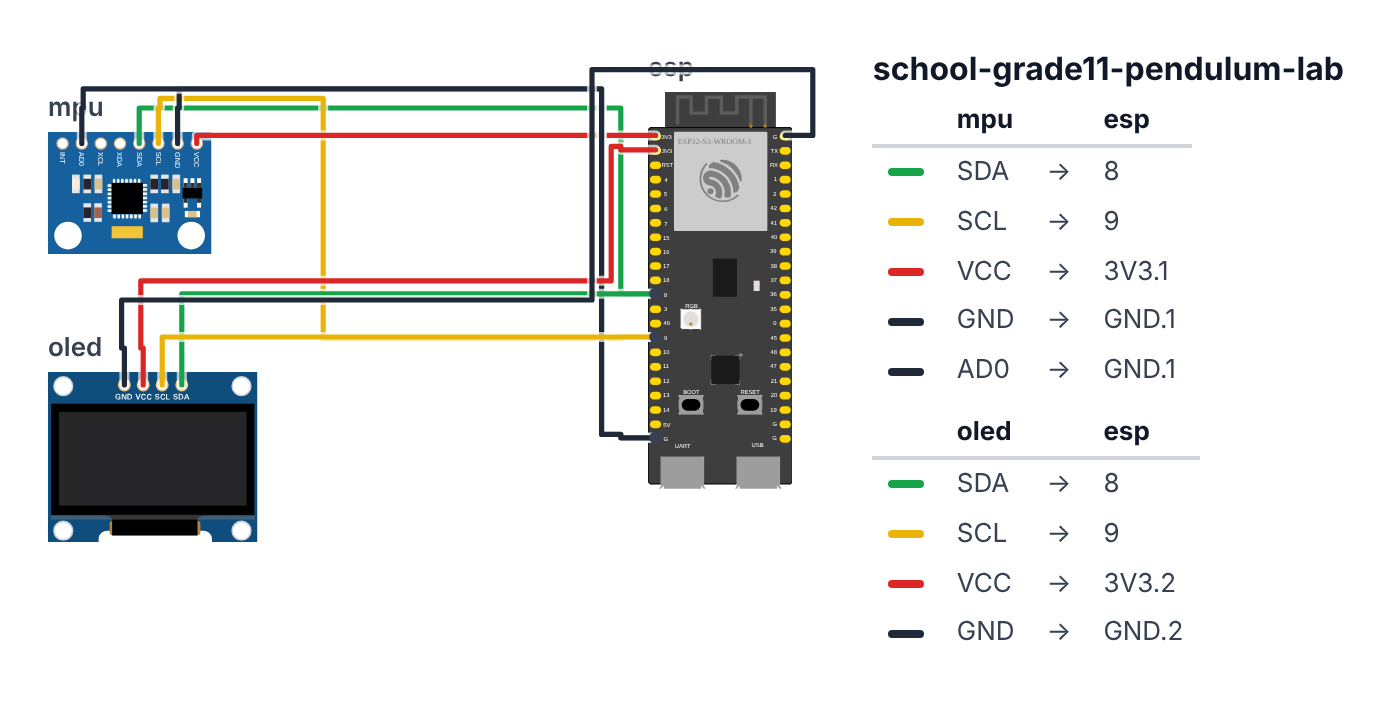
MPU-6050 (I2C):
- SDA → board GPIO 8 (C6: GPIO 6)
- SCL → board GPIO 9 (C6: GPIO 7)
- VCC → 3.3V
- GND → GND
- AD0 → GND (sets I2C address to 0x68)
OLED: 6. SDA → board GPIO 8 (C6: GPIO 6) (same I2C bus) 7. SCL → board GPIO 9 (C6: GPIO 7) (same I2C bus) 8. VCC → 3.3V 9. GND → GND
Check: Both devices on the same I2C bus — MPU-6050 is 0x68, OLED is 0x3C. No conflict.
Step 2: Flash the code
Time: ~20 minutes
Install: MPU6050 (by Electronic Cats), Adafruit SSD1306, Adafruit GFX Library
The big picture first. This program turns the ESP32 into a precision gravity meter:
- The MPU-6050 is an accelerometer strapped to the pendulum. It measures which way the bob is being pulled, 200 times per second.
- The program looks for zero-crossings — the exact moment the pendulum passes through the center (straight down), where horizontal acceleration crosses from positive to negative.
- It records the time of each crossing in microseconds (millionths of a second) and averages them to find a very precise period T.
- Using T and the string length L you measured, it calculates g with the formula g = 4π²L/T².
IMPORTANT: Before uploading, change STRING_LENGTH = 0.50 to your actual string length in meters.
A program is like a recipe. Copy this entire recipe into Arduino IDE and upload it:
// ========== CHOOSE YOUR BOARD ==========
// Uncomment the line for YOUR board:
#define BOARD_S3    // ESP32-S3-DevKitC-1
//#define BOARD_C6  // ESP32-C6-DevKitC-1
// ========================================

#ifdef BOARD_S3
  #define PIN_SDA   8
  #define PIN_SCL   9
#endif
#ifdef BOARD_C6
  #define PIN_SDA   6
  #define PIN_SCL   7
#endif

#include <Wire.h>
#include <MPU6050.h>
#include <Adafruit_GFX.h>
#include <Adafruit_SSD1306.h>

MPU6050 mpu;
Adafruit_SSD1306 display(128, 64, &Wire, -1);

unsigned long lastZeroCross = 0;
unsigned long crossingTimes[200];
int crossingCount = 0;
bool lastPositive = false;

float avgPeriod = 0;
float calculatedG = 0;
float STRING_LENGTH = 0.50;

void updateDisplay() {
  display.clearDisplay();
  display.setTextSize(1);
  display.setCursor(0, 0);
  display.println("Pendulum Lab");

  display.setCursor(0, 12);
  display.println("L=" + String(STRING_LENGTH, 3) + "m");

  if (crossingCount > 2) {
    display.setCursor(0, 24);
    display.println("T=" + String(avgPeriod * 1000.0, 1) + "ms");

    display.setCursor(0, 36);
    display.println("g=" + String(calculatedG, 3) + "m/s2");

    display.setCursor(0, 48);
    int n = crossingCount / 2;
    display.println("n=" + String(n) + " swings");
  } else {
    display.setCursor(0, 28);
    display.println("Waiting for swings...");
    display.setCursor(0, 40);
    display.println("Release pendulum!");
  }

  display.display();
}

void calculateG() {
  if (crossingCount < 4) return;

  long totalTime = crossingTimes[crossingCount-1] - crossingTimes[0];
  int fullPeriods = (crossingCount - 1) / 2;

  if (fullPeriods > 0) {
    avgPeriod = (totalTime / 1000000.0) / fullPeriods;
    calculatedG = 4.0 * PI * PI * STRING_LENGTH / (avgPeriod * avgPeriod);
  }
}

void setup() {
  Serial.begin(115200);
  Wire.begin(PIN_SDA, PIN_SCL);

  mpu.initialize();
  if (!mpu.testConnection()) {
    Serial.println("MPU-6050 not found!"); while(1);
  }
  mpu.setFullScaleAccelRange(MPU6050_ACCEL_FS_2);

  display.begin(SSD1306_SWITCHCAPVCC, 0x3C);
  display.clearDisplay();
  display.setTextSize(1);
  display.setCursor(0, 20);
  display.println("Set STRING_LENGTH");
  display.setCursor(0, 32);
  display.println("in code (meters)!");
  display.setCursor(0, 44);
  display.println("Then re-upload.");
  display.display();
  delay(2000);

  Serial.println("String length (m)," + String(STRING_LENGTH, 3));
  Serial.println("time_us,ax,ay,az");
}

void loop() {
  int16_t ax, ay, az, gx, gy, gz;
  mpu.getMotion6(&ax, &ay, &az, &gx, &gy, &gz);

  float accelX = ax / 16384.0;

  bool positive = (accelX > 0);

  if (positive != lastPositive && crossingCount < 200) {
    unsigned long now = micros();

    if (crossingCount > 0) {
      crossingTimes[crossingCount] = now;
    } else {
      crossingTimes[0] = now;
    }
    crossingCount++;
    lastPositive = positive;

    calculateG();

    Serial.println(String(now) + "," + String(crossingCount) + "," + String(avgPeriod * 1000.0, 2) + "," + String(calculatedG, 4));
  }

  updateDisplay();
  delay(5);
}
Line-by-line: what every line does and why
Lines 1–4: Borrowing ready-made tools
#include <Wire.h>
#include <MPU6050.h>
#include <Adafruit_GFX.h>
#include <Adafruit_SSD1306.h>
#include means “grab this instruction book.” MPU6050.h is the book for talking to the accelerometer. The other three handle I2C communication, graphics drawing, and the OLED display.
Lines 6–7: Naming the sensor and display
MPU6050 mpu;
Adafruit_SSD1306 display(128, 64, &Wire, -1);
These lines create the accelerometer (named mpu) and the screen (named display). Like naming two tools so you can pick up the right one.
Lines 9–16: Boxes for remembering crossings
unsigned long crossingTimes[200];
int crossingCount = 0;
bool lastPositive = false;
crossingTimes[200] is a shelf with 200 slots, each holding a timestamp (in microseconds) of when the pendulum crossed the center. crossingCount is a tally of how many crossings have happened. bool lastPositive is a single light switch — it remembers whether the last accelerometer reading was positive (swinging one way) or negative (swinging the other way). bool means the value is either true or false, nothing else.
Lines 18–20: Results storage
float avgPeriod = 0;
float calculatedG = 0;
float STRING_LENGTH = 0.50;
avgPeriod will hold the average time for one full swing (in seconds). calculatedG will hold our measurement of gravity. STRING_LENGTH is your string length in meters — you must set this before uploading. float means decimal numbers are allowed.
Lines 22–45: updateDisplay() — drawing the screen
if (crossingCount > 2) {
  display.println("T=" + String(avgPeriod * 1000.0, 1) + "ms");
  display.println("g=" + String(calculatedG, 3) + "m/s2");
  int n = crossingCount / 2;
  display.println("n=" + String(n) + " swings");
} else {
  display.println("Waiting for swings...");
}
if means “only do this if the condition is true.” If we have at least 3 crossings, show the results. Otherwise, show “Waiting.” avgPeriod * 1000.0 converts seconds to milliseconds (easier to read). crossingCount / 2 converts half-crossings to full swings — because the pendulum crosses the center twice per full swing (once going right, once going left).
Lines 47–56: calculateG() — the physics calculation
void calculateG() {
  if (crossingCount < 4) return;

  long totalTime = crossingTimes[crossingCount-1] - crossingTimes[0];
  int fullPeriods = (crossingCount - 1) / 2;

  if (fullPeriods > 0) {
    avgPeriod = (totalTime / 1000000.0) / fullPeriods;
    calculatedG = 4.0 * PI * PI * STRING_LENGTH / (avgPeriod * avgPeriod);
  }
}
if (crossingCount < 4) return; says “if we don’t have enough data, stop and do nothing.” return is like a door — it exits the function immediately.
totalTime is the time between the first crossing and the most recent one — like measuring how long the whole run lasted. Dividing by fullPeriods gives the average time per swing.
totalTime / 1000000.0 converts microseconds to seconds (there are one million microseconds in one second).
4.0 * PI * PI * STRING_LENGTH / (avgPeriod * avgPeriod) is the physics formula g = 4π²L/T² that you know from class. PI is the built-in value of π (3.14159…). The computer does the same algebra you do by hand — it just does it thousands of times per second.
Lines 58–77: setup() — the morning routine
mpu.initialize();
if (!mpu.testConnection()) {
  Serial.println("MPU-6050 not found!"); while(1);
}
mpu.setFullScaleAccelRange(MPU6050_ACCEL_FS_2);
mpu.initialize() wakes up the accelerometer. mpu.testConnection() asks “are you there?” The ! means NOT — so if (!mpu.testConnection()) reads “if the sensor did NOT respond.” If the sensor is missing, while(1) freezes the program forever so the error message stays on screen.
MPU6050_ACCEL_FS_2 sets the accelerometer to its most sensitive mode: ±2g. At this setting, the raw number 16384 equals exactly 1g (one gravity). Dividing by 16384.0 converts raw numbers to real g-units.
Lines 79–108: loop() — 200 times per second
int16_t ax, ay, az, gx, gy, gz;
mpu.getMotion6(&ax, &ay, &az, &gx, &gy, &gz);
int16_t is a type of whole number stored in 16 bits — it can hold values from −32768 to +32767. getMotion6 reads all six raw sensor values at once (three for acceleration, three for rotation) and puts them into the six variables.
float accelX = ax / 16384.0;Convert raw sensor number to real gravity units. If ax = 16384, accelX = 1.0 (one g pointing right). If ax = −8192, accelX = −0.5 (half a g pointing left).
bool positive = (accelX > 0);

if (positive != lastPositive && crossingCount < 200) {
positive is true when the pendulum is moving one way, false when moving the other. positive != lastPositive asks “did it just change direction?” The != symbol means “not equal to.” When the answer flips, that means the pendulum just crossed the center point — a zero-crossing detected!
unsigned long now = micros();
crossingTimes[crossingCount] = now;
crossingCount++;
lastPositive = positive;
micros() is a stopwatch that counts microseconds (millionths of a second) since power-on. We save the timestamp, increase the counter by 1 (++), and update lastPositive so the next comparison has the right baseline.
delay(5) at the end means the loop runs every 5 milliseconds — 200 times per second. Fast enough to catch crossings accurately.
The whole thing in one sentence
When powered on, the pendulum lab waits for swings. Every 5ms it reads the accelerometer, detects zero-crossings, and recalculates g. After 10+ swings, the displayed g value is stable and accurate.
First thing to try: hold the pendulum straight down and still. The display should say “Waiting for swings.” Now pull it to about 10° and let go — within 3–4 swings you should see a g value appear. Watch it stabilize as more swings are counted.
IMPORTANT: Set
STRING_LENGTHto your measured string length in meters before uploading. This is the most critical step — a 1cm error in string length causes a 0.4% error in g.
Step 3: Measure string length precisely
Time: ~5 minutes
Measure from the pivot point (where string is attached to the support) to the center of mass of the weight (center of the bolt or washer).
Example: String is 45cm from top to bottom of weight. Weight is 2cm long. String length L = 45 + 1 = 46cm = 0.46m.
Update STRING_LENGTH = 0.46; and re-upload.
Step 4: Run the experiment
- Upload code with correct STRING_LENGTH
- Hold pendulum vertical and still (zero position)
- Pull to small angle (<15°) and release
- Watch the OLED — it should show T and g after 3–4 swings
- Let it run for 50+ swings for a stable average
Expected result: g should be within ±0.5 of 9.81 m/s². If you’re getting 9.4 or 10.2, check:
- Is the string length correct?
- Is the amplitude too large (>20°)?
- Is the pendulum swinging in a plane (not rotating)?
Download Serial data for your lab report. Calculate standard deviation of individual period measurements to report experimental uncertainty.
Presentation tip: Set up the pendulum live during your presentation. Show the OLED updating after each swing. After 10 swings, announce: “Current measured g: [value]. Accepted value: 9.81 m/s². Percent error: [calculate]. The dominant source of error was [string length measurement / swing amplitude / air resistance].”
What just happened
You used zero-crossing detection — finding the moment a continuous signal crosses zero. This is used in power electronics (detecting AC current phase), audio processing (detecting beats), and motor control.
The MPU-6050 communicates via I2C (Inter-Integrated Circuit) — a two-wire protocol that lets multiple sensors share the same bus. The sensor contains MEMS (Micro Electro-Mechanical Systems) — tiny mechanical structures (springs and masses) etched into silicon that deflect when accelerated.
Curriculum connections:
- NGSS HS-PS2-1: Analyze data to support Newton’s second law: F=ma
- AP Physics 1: Simple harmonic motion, period of pendulum, gravitational acceleration
- Common Core Math: Statistical reasoning, uncertainty quantification, percent error
Your measurement of g through careful experimental design demonstrates precision vs. accuracy: precision is your ±0.03 standard deviation; accuracy is how close you are to 9.81.
Level Up
Vary string length: Measure T for 5 different string lengths. Plot T² vs. L — the slope should be 4π²/g. This is a more rigorous determination of g.
Prove small-angle approximation: Increase amplitude to 30°, 45°. Show that T increases for larger amplitudes — the formula T = 2π√(L/g) only works for small angles.
Damping analysis: Log amplitude over time. Fit an exponential decay curve. Calculate the damping coefficient. Compare air resistance vs. string resistance.
Troubleshooting
| Problem | Fix |
|---|---|
| MPU-6050 not found | Check SDA=GPIO 8, SCL=GPIO 9 (C6: SDA=GPIO 6, SCL=GPIO 7). Check 3.3V. Try Wire.begin() before mpu.initialize(). |
| No zero crossings detected | Make sure pendulum is actually swinging. Check that the accelX axis aligns with the swing direction — try az or ay if needed. |
| g reads very wrong (5 or 15) | String length is wrong, or amplitude is too large. |
| Crossings too frequent (noise) | Add a minimum crossing interval: if (now - lastCrossing < 100000) return; |
| Upload fails | Hold BOOT button while clicking Upload. |