Parent info
Parts you need
Affiliate links — we may earn a small commission
Try this circuit in your browser!
Run the code, press the buttons and watch what happens — before you buy any parts. No account needed.
Open in Simulator →Two robots enter the ring. One leaves.
Imagine this: you built a robot. So did your friend. You both put them in a cardboard circle on the living room floor. Three. Two. One. Go. Your robot spins, finds the opponent with its ultrasonic sensor, and charges at full speed. The friend’s robot tries to reverse — but yours has already hit it and pushed it over the white border line.
Match over. You win. Build a second robot and do it again.
That’s what we’re building. In 3 hours. For about $43.
What you’ll need
| Part | What it does | Price |
|---|---|---|
| ESP32-S3 Dev Board | The autonomous brain. Makes decisions at 100Hz. | ~$12 |
| L298N Motor Driver | Drives two wheels independently. | ~$6 |
| HC-SR04 ultrasonic sensor | Detects the opponent up to 50cm away. | ~$3 |
| 2x TCRT5000 IR sensors | Face down — detect the white ring border. Emergency escape. | ~$3 |
| 2x DC geared motors + wheels | Drive the robot. Low-gear = high torque = push harder. | ~$8 |
| 7.4V LiPo battery (2S) | More punch than 9V battery. Lighter too. | ~$10 |
| Resistors: 1kΩ × 1, 2kΩ × 1 | Turn the sonar’s 5V echo into a safe 3.3V for the ESP32. | ~$1 |
Total: ~$43 | Time: ~3 hours | Difficulty: ●●●○○
How it works (60 seconds)
Think of it like this: your robot is playing two games at once — survival and offense.
The ultrasonic sensor in front looks for opponents. If something is within 50 cm — charge at full speed.
But two IR sensors on the bottom point at the floor. When they see the white border of the ring — the white area around the black center — they trigger an emergency reverse + spin. The robot escapes back into the ring.
These two behaviors run in priority order: survival (border detection) always wins over offense (charging). If the robot is pushing an opponent AND about to fall off — it reverses. That’s what separates a competitive robot from one that immediately drives itself out.
The ring takes 10 minutes to make with cardboard and a marker. The matches are over in seconds. You will run at least 20 of them.
Step 0: Build the ring
Time: ~10 minutes
Official mini-sumo specs (build to these or close):
- Diameter: 77 cm
- Center: White (or light) surface
- Border: 5 cm thick black line around the edge
DIY ring: Cut a 77 cm circle from white cardboard or poster board. Draw a thick black border (5 cm wide) with a permanent marker. The robots’ IR sensors detect the white-to-black transition — that’s the border alarm.
Set the ring on a flat floor. Tape it down if needed so it doesn’t slide.
Robot rules: Max size 10×10 cm at start, max weight 500g, no projectiles, no sticky substances. Build within these and any bot you make is competition-legal.
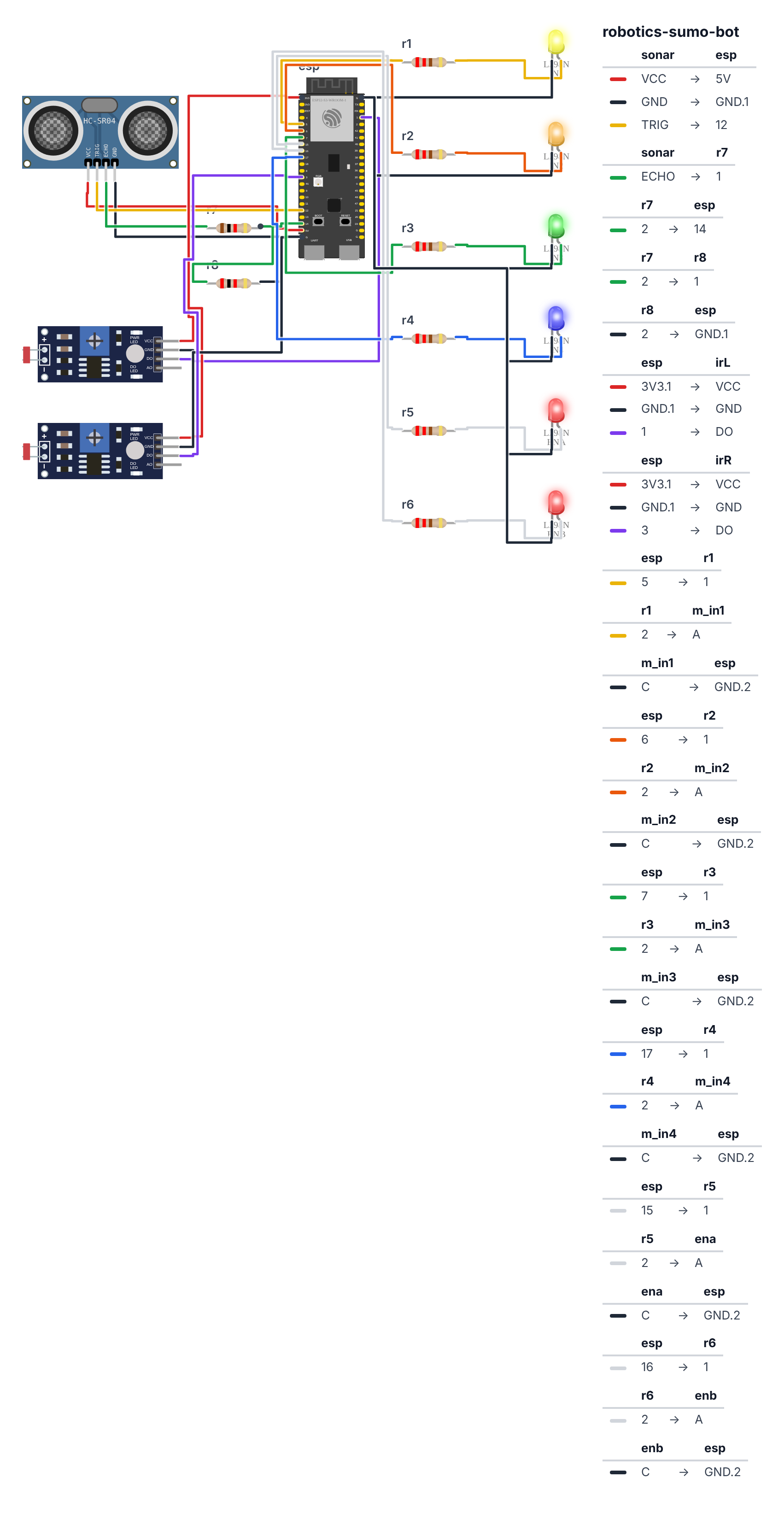
Step 1: Wire it up
Time: ~15 minutes
Motor driver (same as earlier projects):
| ESP32-S3 | ESP32-C6 | L298N Pin | What it does |
|---|---|---|---|
| GPIO 5 | GPIO 19 | IN1 | Left motor forward |
| GPIO 6 | GPIO 20 | IN2 | Left motor backward |
| GPIO 7 | GPIO 22 | IN3 | Right motor forward |
| GPIO 17 | GPIO 23 | IN4 | Right motor backward |
| GPIO 15 | GPIO 3 | ENA | Left motor speed (PWM) |
| GPIO 16 | GPIO 4 | ENB | Right motor speed (PWM) |
HC-SR04 Ultrasonic Sensor (front-facing, at bumper height):
- VCC → 5V (from L298N’s +5V output)
- GND → GND
- TRIG → ESP32 GPIO 12 (C6: GPIO 10)
- ECHO → 1kΩ resistor → ESP32 GPIO 14 (C6: GPIO 11)
- That GPIO side of the 1kΩ → 2kΩ resistor → GND, so the 5V echo signal becomes a safe 3.3V
2x TCRT5000 IR Sensors (underside, near front corners, pointing DOWN at floor):
- Left sensor OUT → ESP32 GPIO 1
- Right sensor OUT → ESP32 GPIO 3 (C6: GPIO 2)
- Both VCC → ESP32 3.3V
- Both GND → ESP32 GND
LiPo battery:
- (+) → L298N 12V terminal
- (−) → L298N GND terminal
Sensor placement matters: The IR sensors must be near the front corners, pointing straight down at the floor. If they’re too far back, the robot will already be half-off the ring before they trigger. Mount them as far forward as possible — within 1 cm of the front edge.
Check: Six control wires to L298N, 4 wires to HC-SR04 (ECHO through the 1kΩ + 2kΩ divider), 4 wires to IR sensors, 2 battery wires. Before powering on, verify LiPo polarity.
Step 2: Flash the code
Time: ~5 minutes
Select ESP32S3 Dev Module in Arduino IDE. Upload:
The big picture first. This program runs a priority stack — two behaviours that always run in the same order:
- Survival first: check if the IR sensors see the white border. If yes, reverse at max speed, spin back to center, and start over.
- Attack second: only if safely inside the ring, check the ultrasonic sensor for opponents. Charge if one is close. Spin to search if not.
This order matters. If the robot checked the attack sensor first, it could drive off the ring while charging. Survival always wins.
// ========== CHOOSE YOUR BOARD ==========
// Uncomment the line for YOUR board:
#define BOARD_S3    // ESP32-S3-DevKitC-1
//#define BOARD_C6  // ESP32-C6-DevKitC-1
// ========================================

#ifdef BOARD_S3
  #define PIN_IN1              5
  #define PIN_IN2              6
  #define PIN_IN3              7
  #define PIN_IN4              17
  #define PIN_ENA              15
  #define PIN_ENB              16
  #define PIN_TRIG             12
  #define PIN_ECHO             14
  #define PIN_IR_L             1
  #define PIN_IR_R             3
#endif
#ifdef BOARD_C6
  #define PIN_IN1              19
  #define PIN_IN2              20
  #define PIN_IN3              22
  #define PIN_IN4              23
  #define PIN_ENA              3
  #define PIN_ENB              4
  #define PIN_TRIG             10
  #define PIN_ECHO             11
  #define PIN_IR_L             1
  #define PIN_IR_R             2
#endif

#define ATTACK_SPEED    230
#define SEARCH_SPEED    160
#define DETECT_DIST     50
#define BORDER_DELAY    350

long readDist() {
  digitalWrite(PIN_TRIG, LOW);  delayMicroseconds(2);
  digitalWrite(PIN_TRIG, HIGH); delayMicroseconds(10);
  digitalWrite(PIN_TRIG, LOW);
  return pulseIn(PIN_ECHO, HIGH, 25000) * 0.034 / 2;
}

void fwd(int spd)  {
  digitalWrite(PIN_IN1,HIGH); digitalWrite(PIN_IN2,LOW);
  digitalWrite(PIN_IN3,HIGH); digitalWrite(PIN_IN4,LOW);
  ledcWrite(PIN_ENA,spd); ledcWrite(PIN_ENB,spd);
}
void rev(int spd)  {
  digitalWrite(PIN_IN1,LOW); digitalWrite(PIN_IN2,HIGH);
  digitalWrite(PIN_IN3,LOW); digitalWrite(PIN_IN4,HIGH);
  ledcWrite(PIN_ENA,spd); ledcWrite(PIN_ENB,spd);
}
void spinLeft(int spd) {
  digitalWrite(PIN_IN1,LOW);  digitalWrite(PIN_IN2,HIGH);
  digitalWrite(PIN_IN3,HIGH); digitalWrite(PIN_IN4,LOW);
  ledcWrite(PIN_ENA,spd); ledcWrite(PIN_ENB,spd);
}
void spinRight(int spd) {
  digitalWrite(PIN_IN1,HIGH); digitalWrite(PIN_IN2,LOW);
  digitalWrite(PIN_IN3,LOW);  digitalWrite(PIN_IN4,HIGH);
  ledcWrite(PIN_ENA,spd); ledcWrite(PIN_ENB,spd);
}
void stopAll() {
  for(int p:{PIN_IN1,PIN_IN2,PIN_IN3,PIN_IN4}) digitalWrite(p,LOW);
  ledcWrite(PIN_ENA,0); ledcWrite(PIN_ENB,0);
}

void setup() {
  Serial.begin(115200);
  for(int p:{PIN_IN1,PIN_IN2,PIN_IN3,PIN_IN4}) pinMode(p,OUTPUT);
  ledcAttach(PIN_ENA,5000,8);
  ledcAttach(PIN_ENB,5000,8);
  pinMode(PIN_TRIG,OUTPUT);
  pinMode(PIN_ECHO,INPUT);
  pinMode(PIN_IR_L,INPUT);
  pinMode(PIN_IR_R,INPUT);

  Serial.println("Sumo Bot — starting in 3 seconds...");
  for(int i=3; i>0; i--) {
    Serial.println(i);
    delay(1000);
  }
  Serial.println("FIGHT!");
}

void loop() {
  bool borderL = (digitalRead(PIN_IR_L) == LOW);
  bool borderR = (digitalRead(PIN_IR_R) == LOW);

  if (borderL || borderR) {
    rev(ATTACK_SPEED);
    delay(BORDER_DELAY);
    if (borderL) spinRight(ATTACK_SPEED);
    else          spinLeft(ATTACK_SPEED);
    delay(250);
    stopAll();
    return;
  }

  long dist = readDist();
  Serial.print("Dist: "); Serial.println(dist);

  if (dist > 0 && dist < DETECT_DIST) {
    fwd(ATTACK_SPEED);
  } else {
    spinRight(SEARCH_SPEED);
    delay(100);
    stopAll();
    delay(50);
  }
}
Line-by-line: what every line does and why
Lines 1–15: Naming pins and tuning numbers
#define ATTACK_SPEED    230
#define SEARCH_SPEED    160
#define DETECT_DIST     50
#define BORDER_DELAY    350
These four numbers are your main tuning controls. ATTACK_SPEED = 230 (out of 255) — nearly full power when charging. SEARCH_SPEED = 160 — slower when spinning to look around, so the bot doesn’t fly past the opponent. DETECT_DIST = 50 cm — charge anything within half a metre. BORDER_DELAY = 350 ms — how long to reverse before spinning. If the bot still falls off, increase this.
readDist(): Sonar trigger
digitalWrite(PIN_TRIG, LOW);  delayMicroseconds(2);
digitalWrite(PIN_TRIG, HIGH); delayMicroseconds(10);
digitalWrite(PIN_TRIG, LOW);
return pulseIn(PIN_ECHO, HIGH, 25000) * 0.034 / 2;
Pull TRIG LOW to clear it, then HIGH for exactly 10 microseconds — this fires the ultrasonic burst. pulseIn waits for ECHO to go HIGH (burst sent) then times how long it stays HIGH (waiting for the echo). Multiply by 0.034 and divide by 2 to get centimetres. The 25000 timeout means “give up after 25ms” — anything beyond ~4 metres returns 0.
Four movement functions
void fwd(int spd)  { ... }
void rev(int spd)  { ... }
void spinLeft(int spd) { ... }
void spinRight(int spd) { ... }
Each function takes a speed number (0–255) and sets all four direction pins accordingly. For spinLeft: left motor runs backward (IN1 LOW, IN2 HIGH) while right motor runs forward (IN3 HIGH, IN4 LOW) — the robot pivots around its centre like a spinning top. spinRight is the mirror image.
setup(): The countdown
for(int i=3; i>0; i--) {
  Serial.println(i);
  delay(1000);
}
Serial.println("FIGHT!");
This for loop counts from 3 down to 1, printing each number with a 1-second pause. i-- reduces i by 1 each time. i > 0 is the condition — stop when i reaches 0. The 3-second delay gives you time to place the robot in the ring and step back before it charges.
loop() — Priority 1: Border detection
bool borderL = (digitalRead(PIN_IR_L) == LOW);
bool borderR = (digitalRead(PIN_IR_R) == LOW);

if (borderL || borderR) {
  rev(ATTACK_SPEED);
  delay(BORDER_DELAY);
  if (borderL) spinRight(ATTACK_SPEED);
  else          spinLeft(ATTACK_SPEED);
  delay(250);
  stopAll();
  return;
}
The TCRT5000 IR sensors point down at the floor. Over the dark ring center they output HIGH. Over the white border they output LOW — white reflects IR more brightly, which confusingly triggers a LOW on most modules. == LOW means “white border detected.” || means OR — trigger if either sensor sees the border. Then: reverse at full speed, wait long enough to clear the border, spin away from the triggered side, stop. return exits loop() immediately — skipping the attack logic entirely. This is the safety guarantee.
loop() — Priority 2: Find and charge
long dist = readDist();
if (dist > 0 && dist < DETECT_DIST) {
  fwd(ATTACK_SPEED);
} else {
  spinRight(SEARCH_SPEED);
  delay(100);
  stopAll();
  delay(50);
}
dist > 0 guards against false zeroes — when pulseIn times out (nothing within range), it returns 0. Treating 0 as “something is 0cm away” would make the robot charge at nothing. The && dist < DETECT_DIST means “AND the distance is less than 50cm.” If both conditions are true, charge. If not, spin right 100ms and stop — this gives a small angular step to scan the ring for the opponent.
The whole thing in one sentence
Every loop iteration: check for the border first (reverse and re-centre if found), then check for opponents (charge if detected, spin-search if not).
First thing to try: Upload the code and open Serial Monitor at 115200 baud. Place the robot on the black part of your ring — Serial should show Dist: XX where XX is the distance to whatever is in front of the sensor. Place your hand 40cm away — watch the number change.
Check: Upload succeeds. Open Serial Monitor at 115200. You should see:
3,2,1,FIGHT!, thenDist: XXnumbers. After 3 seconds, motors activate — keep the robot off the table edge during this test!
Step 3: Calibrate the border sensors
Time: ~5 minutes
Before your first match, test the IR sensors over the actual ring.
- Place the robot on the black border of your ring.
- Check Serial Monitor — it should print something that indicates border detection. The code’s
borderL = (digitalRead(PIN_IR_L) == LOW)assumes LOW = border. If yours is reversed (your sensor gives HIGH over white), change== LOWto== HIGHin both border lines. - Place the robot on the white center. The border alarm should NOT trigger.
Most TCRT5000 modules have a small LED indicator that lights up brightly over white surfaces and dims over black. This is your visual guide — if the LED is lit, it’s seeing white (border). If dim, it’s seeing the dark center (safe).
Step 4: FIGHT!
Place two robots in the ring, facing each other from opposite sides. Both run their 3-second countdown simultaneously. After 3 seconds: they’re autonomous. Neither of you touches them.
Watch the drama unfold.
Strategy tip: The code does spinRight during search. If both robots are doing the same thing, they might circle each other. To counter: change one robot to spinLeft during search. Now they find each other faster.
What just happened (what you learned)
-
Priority-based behavior architecture — The sumo loop checks border first, opponent second. This is a behavioral priority stack — a fundamental pattern in robotics AI. The most critical behavior (survival) always runs before the goal behavior (aggression). If you reversed the order, the robot could drive off the ring while charging. Priority stacking is how you make a robot feel “smart.”
-
Why attack speed for retreat — When the border triggers, the robot reverses at ATTACK_SPEED (230), not the slower SEARCH_SPEED (160). Intentional. A slow reverse gives the opponent time to push you over the edge before you’ve escaped. Maximum urgency on survival behaviors — half-measures are dangerous.
-
Sensor logic inversion — TCRT5000 outputs LOW when seeing high reflectivity (white) on most boards. So “white = danger” becomes
reading == LOW. This opposite-of-a-button logic trips everyone up the first time. Always test sensors in Serial Monitor before trusting them in a match. -
The search strategy is competitive — Spinning right to search is predictable. A smart opponent spinning left finds you faster. Real competition sumo robots use randomized patterns, spiral drives, and sensor arrays. The code gives you a working robot; beating others requires thinking about strategy.
Level Up
Build a second robot and host a tournament. Best of three matches. Adjust ATTACK_SPEED, DETECT_DIST, and BORDER_DELAY differently on each — see which settings win. This is empirical engineering.
Improve the search strategy. Replace spinRight + delay(100) with a forward lunge + slight turn. Drive forward a little, turn slightly, repeat. This creates an expanding arc that covers the ring systematically — harder for the opponent to avoid.
WiFi spectator dashboard. Add WiFi.softAP("SUMO-VIEWER", "fight!"). Serve a page showing current state (SEARCHING / CHARGING / BORDER) and the last distance reading. Watch the HUD during a match — invaluable for debugging why your robot keeps losing.
★★ You completed: Sumo Wrestling Bot!
Troubleshooting
| Problem | Fix |
|---|---|
| Robot drives off the ring immediately | IR border sensors are inverted. Change == LOW to == HIGH in the border detection lines. |
| Robot never detects the border | Sensors too high above the floor — lower them to 2–5mm. Or check 3.3V is connected to IR VCC. |
| Robot ignores opponents at 30cm | Opponent is within DETECT_DIST but pulseIn is returning 0 (timeout). Make sure HC-SR04 VCC is on 5V, not 3.3V. |
| Robot spins randomly instead of charging | Distance reading is always 0 or garbage. Check TRIG on GPIO 12 (C6: GPIO 10) and ECHO on GPIO 14 (C6: GPIO 11). ECHO must go through the 1kΩ + 2kΩ divider (5V echo → safe 3.3V). |
| Match starts before you place robot | Increase startup delay: change delay(1000) in the countdown loop to delay(2000) for a 6-second delay. |
| One motor stronger than the other | One track reaches the border first. Mount the robot more centered, or reduce ATTACK_SPEED slightly (220 instead of 230). |