Parent info
Parts you need
Affiliate links — we may earn a small commission
Try this circuit in your browser!
Run the code, press the buttons and watch what happens — before you buy any parts. No account needed.
Open in Simulator →Your robot ignores you. Completely.
Imagine this: you put a strip of black tape on the floor, press upload, and set the robot down. It takes off — on its own, following the line, making corrections faster than you can see, rounding corners like it knows exactly where it is.
You didn’t touch a joystick. You didn’t press a button. It just goes.
That’s what we’re building. In 2 hours. For about $38.
What you’ll need
| Part | What it does | Price |
|---|---|---|
| ESP32-S3 Dev Board | The brain. Runs the PID loop at 100 times per second. | ~$12 |
| L298N Motor Driver | Lets the ESP32 control two motors — direction and speed. | ~$6 |
| 2x DC geared motors + wheels | Move the robot. Geared = slow enough to control, strong enough to push. | ~$8 |
| 2x TCRT5000 IR sensors | Look at the floor. Black tape = yes. White floor = no. | ~$3 |
| Robot chassis | The body. Wood, acrylic, or 3D-printed. Anything flat works. | ~$4 |
| 9V battery + snap connector | Powers the motors. 9V is plenty for this project. | ~$2 |
| Breadboard + jumper wires | Connects everything without soldering. | ~$3 |
Total: ~$38 | Time: ~2 hours | Difficulty: ●●○○○
How it works (60 seconds)
Think of it like this: your robot drives like you’d walk a tightrope in the dark.
You extend your arms. Left arm detects you’re drifting left — you compensate right. The faster you drift, the harder you compensate. That’s PID control.
Two IR sensors are the robot’s arms. Each one shines invisible infrared light at the floor. White floor reflects it back (bright signal). Black tape absorbs it (weak signal). When the left sensor sees the tape, the robot steers right. When the right sensor sees the tape, it steers left. When both see white — you’re centered, go straight.
The “PID” part makes corrections smooth instead of jerky. Without it, the robot zigzags. With it, it glides.
Step 0: Assemble the chassis
Time: ~20 minutes
Before any electronics, you need a rolling platform.
- Mount both motors to the chassis sides using bolts or hot glue. Motors face outward so the shafts stick out and wheels attach to them.
- Press the wheels onto the motor shafts.
- Add a rear caster wheel (a small ball-bearing roller from a kit, or a bent paperclip as a sled) so the chassis doesn’t drag on its back end.
- Make sure the robot rolls smoothly when pushed by hand. If it resists or veers, check the wheel alignment.
Mount the IR sensors: Attach both TCRT5000 modules to the front underside of the chassis, spaced about 3 cm apart, pointing straight down. They should sit 2–5 mm above the floor. Too high = they lose contrast. Too low = they scrape.
Check: Set the chassis on a white surface. Cover each sensor with your finger one at a time. The small LED on the sensor module should turn ON (or change) when you uncover it over white, and OFF (or dim) over a dark surface. If both LEDs stay on or both stay off, the sensors are wired wrong.
Step 1: Wire it up
Time: ~15 minutes
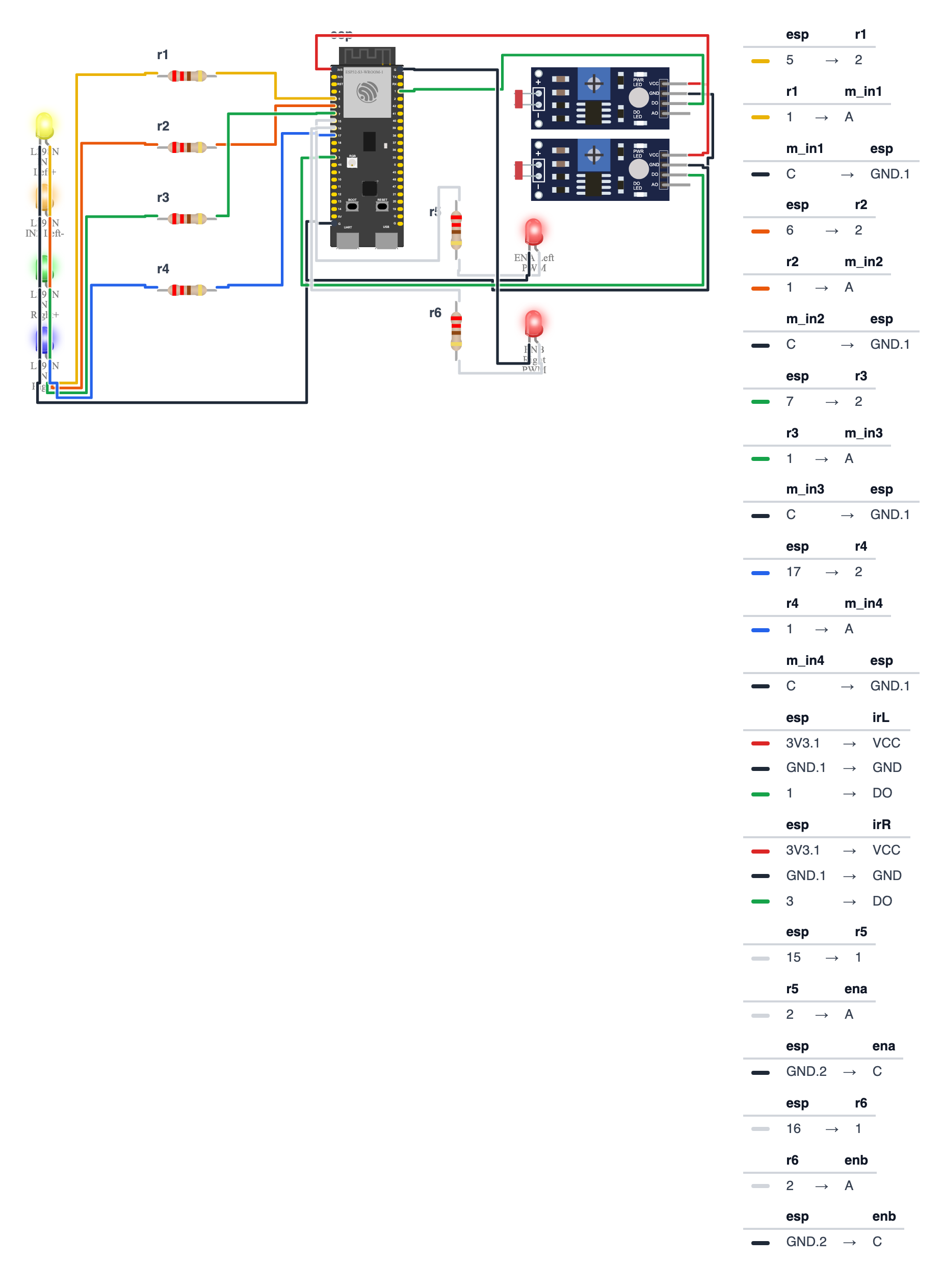
You’re connecting 12 wires total. Work from the pin table.
L298N Motor Driver wiring:
| ESP32-S3 | ESP32-C6 | L298N Pin | Wire Color |
|---|---|---|---|
| GPIO 5 | GPIO 19 | IN1 (Left motor +) | yellow |
| GPIO 6 | GPIO 20 | IN2 (Left motor −) | orange |
| GPIO 7 | GPIO 22 | IN3 (Right motor +) | green |
| GPIO 17 | GPIO 23 | IN4 (Right motor −) | blue |
| GPIO 15 | GPIO 3 | ENA (Left speed PWM) | white |
| GPIO 16 | GPIO 4 | ENB (Right speed PWM) | purple |
| 5V | 5V | +5V (L298N logic power) | red |
| GND | GND | GND | black |
Battery to L298N:
- 9V battery (+) → L298N 12V terminal — red wire
- 9V battery (−) → L298N GND terminal — black wire
Motors to L298N:
- Left motor two wires → L298N OUT1 and OUT2
- Right motor two wires → L298N OUT3 and OUT4
IR sensors (each sensor, 3 wires):
- Left sensor VCC → ESP32 3.3V
- Left sensor GND → ESP32 GND
- Left sensor OUT → ESP32 GPIO 1
- Right sensor OUT → ESP32 GPIO 3 (C6: GPIO 2) (VCC and GND same)
Check: Count your connections. You should have 8 wires to L298N, 6 wires to IR sensors, 2 wires for battery. Double-check the 9V battery goes to L298N (not ESP32 — the ESP32 runs on 3.3V from USB). The ESP32 is powered by USB during development.
Step 2: Flash the code
Time: ~5 minutes
- Install Arduino IDE (free at arduino.cc) and add ESP32 board support under File → Preferences → Board Manager URLs, then add:
https://raw.githubusercontent.com/espressif/arduino-esp32/gh-pages/package_esp32_index.json - Go to Tools → Board → ESP32 Arduino → ESP32S3 Dev Module.
- Connect your ESP32 via USB-C.
- Copy the complete code below, paste it into Arduino IDE, click Upload.
- Open Serial Monitor at 115200 baud.
The big picture first. This program runs a PID control loop — the same algorithm used in cruise control and drone stabilizers. Think of it like this: the robot extends two invisible arms (the IR sensors). Each arm feels the tape. When the left arm feels tape, the robot knows it drifted left and steers right to compensate. PID makes those corrections smooth instead of jerky. The loop runs 100 times per second.
// ========== CHOOSE YOUR BOARD ==========
// Uncomment the line for YOUR board:
#define BOARD_S3    // ESP32-S3-DevKitC-1
//#define BOARD_C6  // ESP32-C6-DevKitC-1
// ========================================

#ifdef BOARD_S3
  #define PIN_IN1              5
  #define PIN_IN2              6
  #define PIN_IN3              7
  #define PIN_IN4              17
  #define PIN_ENA              15
  #define PIN_ENB              16
  #define PIN_IR_LEFT          1
  #define PIN_IR_RIGHT         3
#endif
#ifdef BOARD_C6
  #define PIN_IN1              19
  #define PIN_IN2              20
  #define PIN_IN3              22
  #define PIN_IN4              23
  #define PIN_ENA              3
  #define PIN_ENB              4
  #define PIN_IR_LEFT          1
  #define PIN_IR_RIGHT         2
#endif

#define PWM_FREQ     5000
#define PWM_RES      8

float Kp = 80.0;
float Ki = 0.5;
float Kd = 20.0;

float integral   = 0;
float lastError  = 0;
int   baseSpeed  = 150;

void setup() {
  Serial.begin(115200);

  pinMode(PIN_IN1, OUTPUT);
  pinMode(PIN_IN2, OUTPUT);
  pinMode(PIN_IN3, OUTPUT);
  pinMode(PIN_IN4, OUTPUT);

  ledcAttach(PIN_ENA, PWM_FREQ, PWM_RES);
  ledcAttach(PIN_ENB, PWM_FREQ, PWM_RES);

  pinMode(PIN_IR_LEFT,  INPUT);
  pinMode(PIN_IR_RIGHT, INPUT);

  Serial.println("Line Follower Ready!");
  delay(1000);
}

void setMotors(int leftSpeed, int rightSpeed) {
  leftSpeed  = constrain(leftSpeed,  -255, 255);
  rightSpeed = constrain(rightSpeed, -255, 255);

  if (leftSpeed >= 0) {
    digitalWrite(PIN_IN1, HIGH);
    digitalWrite(PIN_IN2, LOW);
  } else {
    digitalWrite(PIN_IN1, LOW);
    digitalWrite(PIN_IN2, HIGH);
    leftSpeed = -leftSpeed;
  }

  if (rightSpeed >= 0) {
    digitalWrite(PIN_IN3, HIGH);
    digitalWrite(PIN_IN4, LOW);
  } else {
    digitalWrite(PIN_IN3, LOW);
    digitalWrite(PIN_IN4, HIGH);
    rightSpeed = -rightSpeed;
  }

  ledcWrite(PIN_ENA,  leftSpeed);
  ledcWrite(PIN_ENB, rightSpeed);
}

void loop() {
  bool leftSensor  = !digitalRead(PIN_IR_LEFT);
  bool rightSensor = !digitalRead(PIN_IR_RIGHT);

  float error = 0;
  if (leftSensor  && !rightSensor) error =  1.0;
  if (!leftSensor &&  rightSensor) error = -1.0;
  if (!leftSensor && !rightSensor) error =  0.0;
  if ( leftSensor &&  rightSensor) {
    error = lastError;
  }

  integral += error;
  integral  = constrain(integral, -100, 100);

  float derivative = error - lastError;
  float correction = (Kp * error) + (Ki * integral) + (Kd * derivative);
  lastError = error;

  int leftSpeed  = baseSpeed - (int)correction;
  int rightSpeed = baseSpeed + (int)correction;

  setMotors(leftSpeed, rightSpeed);

  Serial.printf("L:%d R:%d  Err:%.2f  Corr:%.2f\n",
    leftSensor, rightSensor, error, correction);

  delay(10);
}
Line-by-line: what every line does and why
Lines 7–26: Naming the pins
#define PIN_IN1              5
...
#define PIN_IR_RIGHT         3
#define gives a number a readable name. These are the ESP32-S3 numbers; the #ifdef BOARD_C6 block has the C6 ones. IN1/IN2 control the left motor direction, IN3/IN4 control the right. ENA/ENB control the speeds. PIN_IR_LEFT and PIN_IR_RIGHT are the two floor sensors that detect the black tape.
Lines 10–14: PWM settings
#define PWM_FREQ     5000
#define PWM_RES      8
The ESP32 controls motor speed using PWM — Pulse Width Modulation. Imagine a light switch flicking on and off 5000 times per second. If it’s on half the time, the motor gets half power. PWM_RES = 8 means speed goes from 0 to 255 (2 to the power of 8 = 256 levels). Each motor’s enable pin gets its own PWM signal.
Lines 16–20: The three PID numbers
float Kp = 80.0;
float Ki = 0.5;
float Kd = 20.0;
float integral = 0;
float lastError = 0;
int   baseSpeed = 150;
These are the three tuning knobs for PID:
- Kp (Proportional) — how hard to correct right now. Like a steering wheel — the farther off-line, the harder you turn.
- Ki (Integral) — how hard to correct for persistent drift. Like noticing one motor is always slightly faster and compensating over time.
- Kd (Derivative) — how hard to resist rapid changes. Like a shock absorber that prevents the robot from bouncing back and forth.
baseSpeed = 150 is how fast both motors run when the robot is centered on the line — think of it as the cruising speed.
setup(): One-time startup
ledcAttach(PIN_ENA, PWM_FREQ, PWM_RES);ledcAttach sets up PWM on the ENA speed pin with frequency 5000 Hz and 8-bit resolution (0–255). In one call it creates the PWM channel and connects it to the pin. The ESP32 does not have a simple analogWrite() like some other boards — it uses a dedicated LEDC (LED Control) hardware block instead. Despite the name, it works for any PWM purpose.
setMotors(int leftSpeed, int rightSpeed): Sending speed to the motors
leftSpeed = constrain(leftSpeed, -255, 255);
if (leftSpeed >= 0) { digitalWrite(PIN_IN1, HIGH); ... }
else { ... leftSpeed = -leftSpeed; }
ledcWrite(PIN_ENA,  leftSpeed);
constrain is like a guardrail — it clips the number so it never goes below -255 or above 255. Direction and speed are handled separately: the if/else sets direction by flipping the two pins (like choosing which direction current flows through the motor). Then ledcWrite sets the speed. When the number is negative, we flip the pins first and then convert it to positive before setting PWM — you can’t have a negative duty cycle.
loop() — Sensor reading
bool leftSensor  = !digitalRead(PIN_IR_LEFT);
bool rightSensor = !digitalRead(PIN_IR_RIGHT);
digitalRead returns HIGH (1) or LOW (0). The TCRT5000 sensor outputs LOW when it sees black tape (the tape absorbs the infrared light) and HIGH over white floor (white reflects). The ! (NOT) flips this so that leftSensor = true means “the left sensor IS on the black tape” — which is more intuitive to read.
loop() — Error calculation
if (leftSensor  && !rightSensor) error =  1.0;
if (!leftSensor &&  rightSensor) error = -1.0;
if (!leftSensor && !rightSensor) error =  0.0;
if ( leftSensor &&  rightSensor) { error = lastError; }
error describes how far off the line the robot is. Read it like a doctor’s chart:
- Left sensor on tape, right sensor off → robot drifted left →
error = +1.0(steer right) - Right sensor on tape, left sensor off → robot drifted right →
error = -1.0(steer left) - Both sensors off tape → centered! →
error = 0.0 - Both on tape → crossed a T-junction → keep going the same direction as before (
lastError)
&& means AND. || would mean OR.
loop() — The PID math
integral += error;
integral  = constrain(integral, -100, 100);
float derivative = error - lastError;
float correction = (Kp * error) + (Ki * integral) + (Kd * derivative);
lastError = error;
Three lines of math that are the heart of the whole program:
integral += error— adds today’s error to a running total. Like keeping a running score — if the robot has been drifting left for 50 loops,integralgets large.constrain(integral, -100, 100)— caps the total so it doesn’t grow forever. Without this, a stuck robot would build an enormous integral that causes wild overcorrection when it finally gets free.derivative = error - lastError— how fast the error is changing. If the robot was perfectly centered last loop and is suddenly way off, the derivative is large andKdfights it hard.correction = (Kp × error) + (Ki × integral) + (Kd × derivative)— combine all three into one steering command.
loop() — Applying the correction
int leftSpeed  = baseSpeed - (int)correction;
int rightSpeed = baseSpeed + (int)correction;
setMotors(leftSpeed, rightSpeed);
baseSpeed is the cruising speed (150). Subtract correction from the left motor and add it to the right. When correction is positive (robot drifted left), the left motor slows and the right motor speeds up — the robot steers right. It’s like leaning on one side of a bicycle to turn.
The whole thing in one sentence
The robot reads two floor sensors 100 times per second, calculates how far off the line it is and how fast it’s drifting, and adjusts the two motor speeds to always steer back toward center.
First thing to try: Upload the code and open Serial Monitor at 115200 baud. Without a track, place the robot on white floor — you should see Err:0.00. Now place a piece of black tape under the left sensor — the error should jump to 1.00 and the correction should show a positive number.
Check: Upload succeeds with no red errors. Serial Monitor shows
Line Follower Ready!then numbers likeL:0 R:0 Err:0.00 Corr:0.00.
Step 3: Make the track
Time: ~5 minutes
Use 19 mm or 25 mm black electrical tape on a white floor or large piece of white paper.
- Minimum curve radius: 15 cm — tighter corners are hard to follow at first
- Start with a simple oval — it’s the easiest shape to tune on
- Make sure the tape has no air bubbles and sits flat — bumps confuse the sensors
Step 4: Tune and race!
Time: ongoing — the fun part
Put the robot on the white area just before the tape. Power everything (USB for ESP32, 9V battery for motors). Watch the Serial Monitor numbers as the robot moves.
First run — expect it to wiggle. That’s normal. The default PID values (Kp=80, Ki=0.5, Kd=20) are a starting point.
Tuning method:
- Set Ki=0 and Kd=0 in the code. Upload.
- Increase Kp until the robot oscillates wildly around the line — that’s your maximum P.
- Set Kp to about 70% of that maximum.
- Now increase Kd until the oscillation damps out (robot tracks smoothly).
- Finally, add a tiny Ki (start at 0.1) to correct drift on long straights.
Each upload takes 30 seconds. Within 4–5 uploads, your robot will be tracking the line like it’s on rails.
Common issue: If one wheel consistently runs faster than the other on a straight, one of your motors is slightly different. Increase Ki slightly (0.5 → 1.0) — the integral term corrects persistent drift exactly like this.
What just happened (what you learned)
You might not realize it, but you just used some serious real-world concepts:
-
PID control — the same algorithm in cruise control, drone stabilization, and industrial robots. P = how far off you are right now. I = how long you’ve been off. D = how fast you’re drifting. The sum gives a correction that adapts to conditions automatically.
-
L298N H-bridge internals — four transistors in an H shape. IN1/IN2 control which transistors conduct, setting motor direction. ENA controls how much current flows via PWM — that controls speed. Direction and speed are completely independent.
-
ESP32 LEDC peripheral — the ESP32 doesn’t have
analogWrite(). Instead it has the LEDC hardware timer:ledcAttach()configures and connects it to a GPIO in one step,ledcWrite()sets the duty cycle. 8-bit = 0–255. 5000 Hz so you can’t hear the motor whine. -
TCRT5000 infrared sensing — the sensor has an IR LED (always on) and a phototransistor. White surfaces reflect IR strongly → HIGH output. Black surfaces absorb IR → LOW output. Every line-following robot ever made uses this principle.
Level Up
5-sensor array: Add 3 more TCRT5000 sensors across the front. Now you get error values of −2, −1, 0, +1, +2 for smoother gradient control. Competition robots use 5–8 sensors for this reason.
Lap timer: Mount one sensor pointing up at a fixed point on the track (like a start/finish bridge). Use a hardware interrupt to record millis() every time the robot passes. Calculate lap time as the difference. Display fastest lap on an OLED. Now you have a proper time trial.
Speed mode: Wire a button to a spare GPIO. Short press = fast mode (baseSpeed=200). Long press = slow mode (baseSpeed=100). Same track, two challenges.
★★ You completed: Line Follower Robot!
Troubleshooting
| Problem | Fix |
|---|---|
| Robot doesn’t move at all | Check the 9V battery is connected to L298N (not ESP32). Check IN1–IN4 wiring. Open Serial Monitor — if it prints numbers, the code is running. |
| One motor spins, other doesn’t | Swap OUT1/OUT2 wires on L298N. If still stuck, check GPIO 7 and 17 (C6: GPIO 22 and 23) are wired to IN3/IN4. |
| Robot goes backward instead of forward | Swap both wire pairs on both motor outputs (OUT1/OUT2 and OUT3/OUT4). |
| Robot ignores the line | Check IR sensor height: 2–5 mm above floor. Check sensors read in Serial Monitor (cover with finger — number changes). Check 3.3V powers IR VCC (not 5V). |
| Robot oscillates wildly on the line | Reduce Kp. Set Ki=0 and Kd=0, then tune from scratch. |
| Robot falls off straight sections | One motor is slightly slower. Increase Ki from 0.5 to 1.0–2.0. |
| Upload fails | Check USB-C cable is data capable (not charge-only). Select ESP32S3 Dev Module in Tools → Board. |