Parent info
Parts you need
Affiliate links — we may earn a small commission
Try this circuit in your browser!
Run the code, press the buttons and watch what happens — before you buy any parts. No account needed.
Open in Simulator →You move a fader. Ableton’s reverb changes. You made the hardware.
Imagine this: a flat panel on your desk — six faders in a row, six buttons below them, one encoder in the corner. You open Ableton Live. You move fader 1 — the volume fader on Track 1 responds. You push fader 3 up — the filter cutoff sweeps open. You press button 2 — a sample triggers.
You just built a MIDI controller. The commercial version costs $80–$150. Yours costs $20 and you can reprogram every parameter any time you want.
What you’ll need
| Part | What it does | Price |
|---|---|---|
| ESP32-S3 Dev Board | Brain — ESP32-S3 only. The S3’s native USB makes it appear as a real MIDI device — no drivers needed. | ~$12 |
| 6× 10kΩ slide potentiometers (60mm) | Physical faders — each sends MIDI Control Change messages. | ~$4 |
| 6× tactile buttons | Trigger notes or toggle functions. | ~$1 |
| Rotary encoder | Mod wheel — continuous control, no end stops. | ~$1 |
| 0.96” OLED (SSD1306 I2C) | Shows all 6 CC values as bar charts + current mod wheel position. | ~$2 |
Total: ~$20 | Time: ~3 hours | Difficulty: ●●●○○
Important: This project is ESP32-S3 only — the S3 has native USB hardware (USB OTG) that lets the board show up as a USB-MIDI device. The classic ESP32 and the ESP32-C6 don’t have it (the C6’s USB port can only do serial and uploads), so they can’t run this project — if you pick the C6 in the sketch, it stops with a friendly error message. Look for “S3” on your board.
How it works (60 seconds)
Think of MIDI like a universal musical language — a list of simple messages.
“Note On, note 60, velocity 127” = middle C, played hard. “Control Change, controller 7, value 64” = volume at half. Every DAW (Ableton, GarageBand, Logic, FL Studio) speaks this language fluently.
The ESP32-S3’s USB hardware can tell your computer “I’m a MIDI interface.” Your computer loads its built-in MIDI driver. Now your physical faders and buttons speak directly to any software that understands MIDI — no custom drivers, no configuration. Just plug in and MIDI-map.
Each fader converts its physical position (0 to full) to a MIDI CC value (0 to 127). Move the fader — the DAW parameter it’s mapped to follows.
Step 0: Plan your MIDI mapping
Time: ~5 minutes
Before wiring, decide what each fader controls. You can change this in Ableton’s MIDI Map mode any time, but having a mental model helps.
Suggested default mapping:
- Fader 0 → CC 7 (Main Volume — every DAW knows this)
- Fader 1 → CC 10 (Pan)
- Fader 2 → CC 11 (Expression)
- Faders 3–5 → CC 12–14 (custom — map to filter cutoff, reverb send, delay mix)
- Encoder → CC 1 (Mod Wheel — standard)
- Buttons → MIDI Notes 36–41 (standard GM drum notes: kick, snare, hi-hat…)
Step 1: Wire it up
Time: ~20 minutes
ESP32-S3 only: all pins below are for the ESP32-S3-DevKitC-1. The C6’s USB port can only do serial and uploads (no USB OTG), so it can’t be a USB-MIDI device.
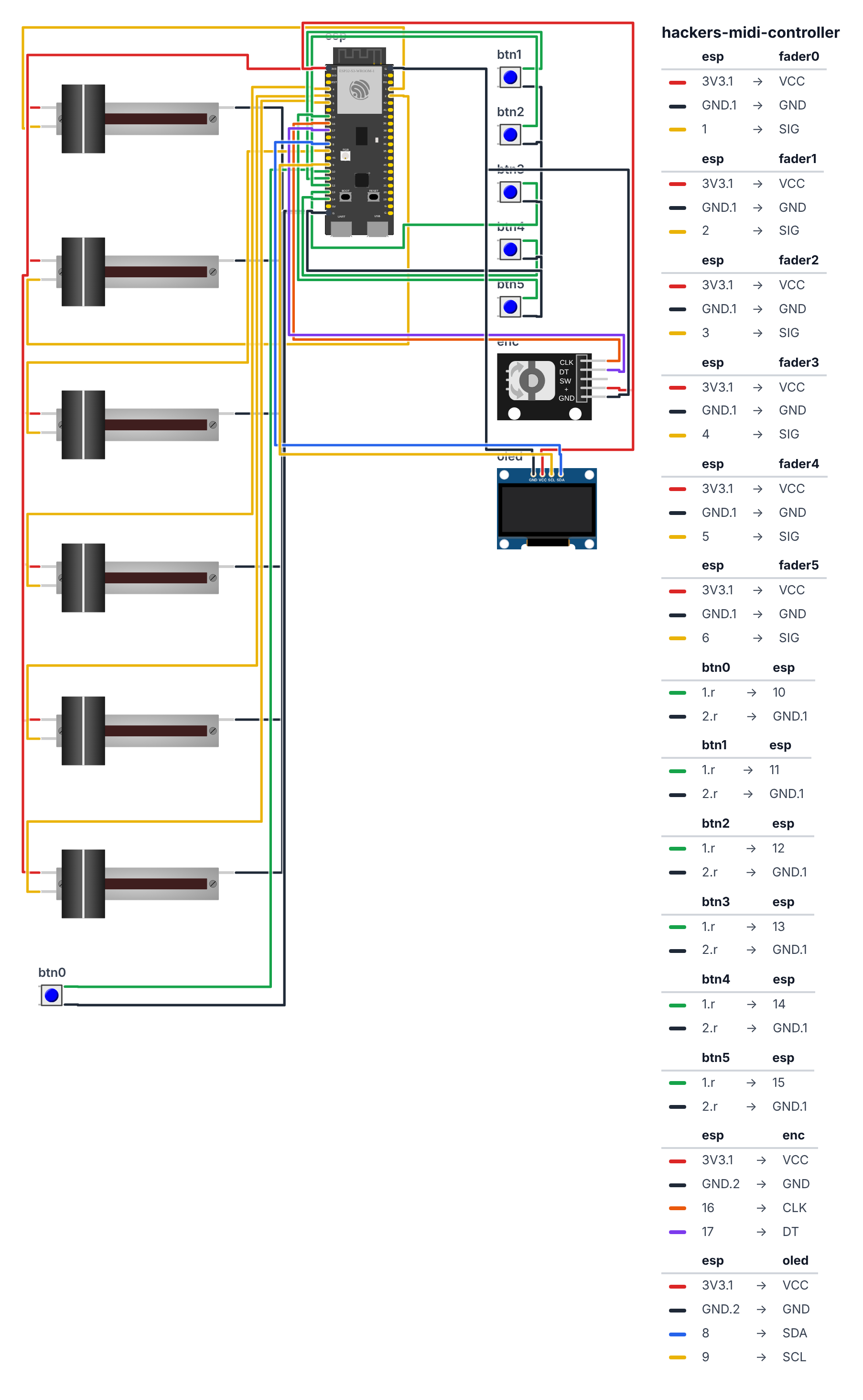
Slide Potentiometers (3 wires each, 6 total): For each fader:
- One end → 3.3V
- Other end → GND
- Wiper (middle pin) → ADC pin
- Fader 0 wiper → GPIO 1
- Fader 1 wiper → GPIO 2
- Fader 2 wiper → GPIO 3
- Fader 3 wiper → GPIO 4
- Fader 4 wiper → GPIO 5
- Fader 5 wiper → GPIO 6
Buttons (2 wires each, 6 total): 7. Button 0 → GPIO 10 | other leg → GND 8. Button 1 → GPIO 11 | other leg → GND 9. Button 2 → GPIO 12 | other leg → GND 10. Button 3 → GPIO 13 | other leg → GND 11. Button 4 → GPIO 14 | other leg → GND 12. Button 5 → GPIO 15 | other leg → GND
Rotary Encoder (5 wires): 13. Encoder CLK → GPIO 16 14. Encoder DT → GPIO 17 15. Encoder + → 3.3V 16. Encoder GND → GND
OLED (4 wires): 17. OLED SDA → GPIO 8 18. OLED SCL → GPIO 9 19. OLED VCC → 3.3V 20. OLED GND → GND
Check: Fader ADC pins (GPIO 1–6) should have
INPUTmode, NOTINPUT_PULLUP— analog inputs must float freely. Button GPIO pins useINPUT_PULLUP. Do not confuse them.
Step 2: Install libraries and flash
Time: ~10 minutes
Install in Arduino IDE Library Manager:
- USB-MIDI by lathoub — makes ESP32-S3 appear as a USB MIDI device
- Adafruit SSD1306 + Adafruit GFX Library — OLED
Select board: ESP32S3 Dev Module
The big picture first. MIDI is a musical language invented in 1983 — a list of simple messages like “note on,” “note off,” and “knob moved.” The ESP32-S3’s USB hardware can pretend to be a MIDI interface — when you plug it into your computer, the computer asks “what are you?” and the board answers “I’m a MIDI controller.” Your computer loads its built-in MIDI driver instantly, no extra software needed. Then every DAW — Ableton, GarageBand, Logic — can receive messages from your faders and buttons. The faders are potentiometers: resistors with a sliding wiper that divides voltage. The ESP32’s ADC reads that voltage as a number from 0 to 4095. The code converts that to 0–127 (MIDI’s range) and sends it as a Control Change message. The clever part: the ADC has small random noise — readings jitter even when the fader is perfectly still. Without a dead zone check, this floods your DAW with thousands of tiny identical messages per second. The > 2 check stops that.
// ========== CHOOSE YOUR BOARD ==========
// Uncomment the line for YOUR board:
#define BOARD_S3    // ESP32-S3-DevKitC-1
//#define BOARD_C6  // ESP32-C6-DevKitC-1
// ========================================

#ifdef BOARD_S3
  #define PIN_FADER0           1
  #define PIN_FADER1           2
  #define PIN_FADER2           3
  #define PIN_FADER3           4
  #define PIN_FADER4           5
  #define PIN_FADER5           6
  #define PIN_BTN0             10
  #define PIN_BTN1             11
  #define PIN_BTN2             12
  #define PIN_BTN3             13
  #define PIN_BTN4             14
  #define PIN_BTN5             15
  #define PIN_ENC_CLK          16
  #define PIN_ENC_DT           17
  #define PIN_SDA              8
  #define PIN_SCL              9
#endif
#ifdef BOARD_C6
  #error "USB MIDI needs a USB OTG port, and the ESP32-C6 doesn't have one (its USB only does serial and uploads). This project is ESP32-S3 only: pick BOARD_S3 at the top."
#endif

#include <Wire.h>
#include <Adafruit_SSD1306.h>
#include <USB-MIDI.h>

USBMIDI_CREATE_DEFAULT_INSTANCE();

const int FADER_PINS[6] = {PIN_FADER0, PIN_FADER1, PIN_FADER2, PIN_FADER3, PIN_FADER4, PIN_FADER5};
const int BTN_PINS[6]   = {PIN_BTN0, PIN_BTN1, PIN_BTN2, PIN_BTN3, PIN_BTN4, PIN_BTN5};
const int ENC_CLK = PIN_ENC_CLK, ENC_DT = PIN_ENC_DT;

const int CC_FADERS[6]  = {7, 10, 11, 12, 13, 14};
const int MIDI_CHANNEL  = 1;

int lastFaderVal[6] = {-1};
int lastBtnVal[6]   = {HIGH};
int ccValues[6]     = {0};
int encLastCLK;

Adafruit_SSD1306 display(128, 64, &Wire, -1);

volatile int masterCC = 64;
void IRAM_ATTR encoderISR() {
  int clk = digitalRead(ENC_CLK);
  int dt  = digitalRead(ENC_DT);
  if (clk != encLastCLK && clk == 0) {
    if (dt != clk) masterCC = min(127, masterCC + 1);
    else           masterCC = max(0,   masterCC - 1);
    MIDI.sendControlChange(1, masterCC, MIDI_CHANNEL);
    encLastCLK = clk;
  }
}

void setup() {
  MIDI.begin(MIDI_CHANNEL_OMNI);

  for (int i = 0; i < 6; i++) {
    pinMode(FADER_PINS[i], INPUT);
    pinMode(BTN_PINS[i], INPUT_PULLUP);
  }

  pinMode(ENC_CLK, INPUT_PULLUP);
  pinMode(ENC_DT,  INPUT_PULLUP);
  encLastCLK = digitalRead(ENC_CLK);
  attachInterrupt(digitalPinToInterrupt(ENC_CLK), encoderISR, CHANGE);

  Wire.begin(PIN_SDA, PIN_SCL);
  display.begin(SSD1306_SWITCHCAPVCC, 0x3C);
  display.setTextColor(WHITE);
}

void loop() {
  MIDI.read();

  for (int i = 0; i < 6; i++) {
    int raw = analogRead(FADER_PINS[i]);
    int ccVal = map(raw, 0, 4095, 0, 127);

    if (abs(ccVal - lastFaderVal[i]) > 2) {
      MIDI.sendControlChange(CC_FADERS[i], ccVal, MIDI_CHANNEL);
      ccValues[i] = ccVal;
      lastFaderVal[i] = ccVal;
    }
  }

  for (int i = 0; i < 6; i++) {
    int val = digitalRead(BTN_PINS[i]);
    if (val != lastBtnVal[i]) {
      delay(10);
      val = digitalRead(BTN_PINS[i]);
      if (val != lastBtnVal[i]) {
        if (val == LOW) {
          MIDI.sendNoteOn(36 + i, 127, MIDI_CHANNEL);
        } else {
          MIDI.sendNoteOff(36 + i, 0, MIDI_CHANNEL);
        }
        lastBtnVal[i] = val;
      }
    }
  }

  static unsigned long lastDisplay = 0;
  if (millis() - lastDisplay > 50) {
    lastDisplay = millis();
    display.clearDisplay();
    display.setTextSize(1);
    display.setCursor(0, 0);
    display.print("MIDI CTRL");
    display.setCursor(80, 0);
    display.print("MOD:");
    display.print(masterCC);

    for (int i = 0; i < 6; i++) {
      int barH = map(ccValues[i], 0, 127, 0, 50);
      int bx = i * 20 + 4;
      display.drawRect(bx, 12, 14, 52, WHITE);
      display.fillRect(bx + 1, 12 + (50 - barH) + 2, 12, barH, WHITE);
      display.setTextSize(1);
      display.setCursor(bx + 2, 57);
      display.print(i + 1);
    }
    display.display();
  }

  delay(5);
}
Line-by-line: what every line does and why
Creating the MIDI device
USBMIDI_CREATE_DEFAULT_INSTANCE();This one line does something extraordinary: it tells the ESP32-S3’s USB hardware to announce itself to your computer as a MIDI interface. When you plug in the USB cable, your computer asks “what kind of device are you?” The USB-MIDI library answers “I’m a class-compliant MIDI interface.” Your computer loads its built-in MIDI driver instantly — no extra software, no configuration. Every DAW that exists already knows how to talk to this type of device.
Arrays: organizing 6 faders and 6 buttons
const int FADER_PINS[6] = {PIN_FADER0, PIN_FADER1, PIN_FADER2, PIN_FADER3, PIN_FADER4, PIN_FADER5};
const int BTN_PINS[6]   = {PIN_BTN0, PIN_BTN1, PIN_BTN2, PIN_BTN3, PIN_BTN4, PIN_BTN5};
const int CC_FADERS[6]  = {7, 10, 11, 12, 13, 14};
Arrays are lists. FADER_PINS[0] is PIN_FADER0 (GPIO 1), FADER_PINS[1] is PIN_FADER1 (GPIO 2), and so on. Instead of writing six separate pieces of code for six separate faders, you write one loop and let the array tell you which pin to use. CC_FADERS maps each fader to its MIDI CC number — CC7 is standard volume, CC10 is standard pan. These are universally understood by all DAWs.
int lastFaderVal[6] = {-1};-1 is a trick. Valid CC values are 0–127, so -1 is impossible. On the very first loop, every fader will read a real value (say, 0), and since 0 != -1, the initial CC value gets sent to the DAW. This forces all faders to report their position immediately at startup.
encoderISR — the mod wheel interrupt
volatile int masterCC = 64;
void IRAM_ATTR encoderISR() {
  int clk = digitalRead(ENC_CLK);
  int dt  = digitalRead(ENC_DT);
  if (clk != encLastCLK && clk == 0) {
    if (dt != clk) masterCC = min(127, masterCC + 1);
    else           masterCC = max(0,   masterCC - 1);
    MIDI.sendControlChange(1, masterCC, MIDI_CHANNEL);
    encLastCLK = clk;
  }
}
volatile means “this variable can change at any moment from outside the normal code flow — never use a cached copy, always read the real current value from memory.” The interrupt fires the instant the encoder CLK pin changes state, regardless of what the main loop is doing. IRAM_ATTR stores this function in fast-access RAM so it runs in nanoseconds.
masterCC = 64 starts the mod wheel at center (MIDI’s range is 0–127, center is 64). Each encoder click adds or subtracts 1. MIDI.sendControlChange(1, masterCC, MIDI_CHANNEL) sends CC1 — the standard Mod Wheel message. Most synthesizer plugins assign vibrato, filter sweep, or expression to CC1 by default.
setup — starting MIDI and configuring pins
MIDI.begin(MIDI_CHANNEL_OMNI);MIDI_CHANNEL_OMNI means “listen on all 16 MIDI channels.” We are primarily sending, not receiving, but calling MIDI.begin() initializes the USB MIDI system and keeps the library happy.
    pinMode(FADER_PINS[i], INPUT);
    pinMode(BTN_PINS[i], INPUT_PULLUP);
This is the critical difference. Fader pins use INPUT — no internal resistor. Analog pins must float freely to read the voltage from the potentiometer’s wiper. If you accidentally used INPUT_PULLUP, you would connect an internal resistor to 3.3V and the ADC would always read near-maximum, ignoring the fader. Button pins use INPUT_PULLUP — the pin is normally HIGH (3.3V through internal resistor), goes LOW when you press the button to GND.
loop — reading faders with dead zone
    int raw = analogRead(FADER_PINS[i]);
    int ccVal = map(raw, 0, 4095, 0, 127);
analogRead returns 0–4095 (12-bit ADC — 4096 possible values). map(raw, 0, 4095, 0, 127) scales this to 0–127 (MIDI’s 7-bit range). Think of it as converting a thermometer from Celsius to Fahrenheit — same physical value, different scale.
    if (abs(ccVal - lastFaderVal[i]) > 2) {
      MIDI.sendControlChange(CC_FADERS[i], ccVal, MIDI_CHANNEL);
      ccValues[i] = ccVal;
      lastFaderVal[i] = ccVal;
    }
abs() gives the absolute difference — always positive. If the fader moved by more than 2 CC steps, send the message and update the stored value. A fader sitting still might read 63, 64, 63, 64… — a difference of 1, which the > 2 check ignores. This prevents flooding your DAW with thousands of tiny identical messages per second.
loop — reading buttons
      delay(10);
      val = digitalRead(BTN_PINS[i]);
      if (val != lastBtnVal[i]) {
        if (val == LOW) {
          MIDI.sendNoteOn(36 + i, 127, MIDI_CHANNEL);
        } else {
          MIDI.sendNoteOff(36 + i, 0, MIDI_CHANNEL);
        }
After detecting a change, wait 10 milliseconds and read again. This is debouncing — physical buttons bounce electrically for a few milliseconds when pressed. The second read confirms the button is genuinely in its new state.
MIDI.sendNoteOn(36 + i, 127, MIDI_CHANNEL) — note 36 is kick drum in the GM drum map, 37 is snare, 38 is hand clap, and so on. Velocity 127 is maximum force — like pressing a piano key as hard as possible. MIDI.sendNoteOff is sent when the button is released.
loop — OLED bar chart
      int barH = map(ccValues[i], 0, 127, 0, 50);
      int bx = i * 20 + 4;
      display.drawRect(bx, 12, 14, 52, WHITE);
      display.fillRect(bx + 1, 12 + (50 - barH) + 2, 12, barH, WHITE);
Each fader gets a 14-pixel wide column on the OLED. drawRect draws the empty container. fillRect draws the filled portion inside it. The y-position math 12 + (50 - barH) + 2 makes the bar grow from bottom to top (higher CC value = bar rises from the bottom up) — like a real mixing desk where pushing the fader up increases volume.
The whole thing in one sentence
Six physical faders read their positions, convert them to 0–127, and send MIDI Control Change messages to your DAW — but only when they actually move — while six buttons send Note On and Note Off, an encoder knob sends mod wheel, and a bar chart on the OLED shows all six fader positions at a glance.
First thing to try: Upload, plug the USB cable into your computer, open GarageBand or Ableton, right-click any knob, click “Learn Assignment” or “MIDI map,” then move fader 1 — the knob should immediately follow the fader’s position.
Check: After upload, open System Information (Mac) or Device Manager (Windows) and look for a MIDI device. The ESP32-S3 should appear as a class-compliant MIDI interface.
Step 3: Map faders to your DAW
Time: ~5 minutes
In Ableton Live:
- Click the MIDI button in the top bar (or press Cmd/Ctrl + M)
- Click any knob, fader, or button in Ableton that you want to control
- Move your physical fader — Ableton shows the incoming CC number and maps it
- Click MIDI mode off. Done.
In GarageBand:
- Open a Smart Controls panel
- Right-click any knob → Learn Assignment
- Move your fader
In Logic Pro:
- View → Show Smart Controls
- Right-click any knob → Learn MIDI
Your physical fader now controls that exact parameter. Move it while recording — that’s hardware automation.
Step 4: Use it!
Volume mixing: Map faders 0–5 to volume CC7 on MIDI channels 1–6. Now you have a physical mixing desk — each fader controls a different track’s volume.
Effect control: Map faders to filter cutoff (usually CC 74), reverb send (varies by plugin), or delay mix. Move them while playing a loop and automate in real time.
Live performance: Buttons 0–5 trigger samples or notes. In combination with a software sampler, you’ve built a basic pad controller.
Mod wheel: The encoder controls CC1 (standard mod wheel) — most synthesizer plugins use this for vibrato, filter, or expression. Turn while holding a key.
What just happened (what you learned)
-
MIDI (Musical Instrument Digital Interface) — a 40-year-old protocol that hasn’t changed because it’s perfect. Simple messages: “note on, note off, knob moved” between instruments and software. 7-bit values (0–127) for everything. Volume, pitch, effects — all 0 to 127.
-
ADC jitter — the ESP32’s 12-bit analog-to-digital converter reads 4096 different values but has about 1–2 bits of noise. A fader sitting still might read 1000, 1001, 999… This creates a constant stream of tiny MIDI messages that floods your DAW. The
> 2dead zone catches these — only real movement sends messages. -
USB-HID enumeration — when you plug in the ESP32-S3, your computer asks “what kind of device are you?” The USB-MIDI library answers “I’m a MIDI interface.” Your computer loads a built-in driver. Every DAW can receive messages from your physical faders, instantly.
-
CC vs. Note — Control Change (CC) messages are for continuous controllers (faders, knobs). They have a controller number and a value (0–127). Note On/Off are for triggers (buttons, keys). Using Notes for buttons is correct — they have “on when pressed, off when released” semantics.
Level Up
Add velocity sensitivity. Buttons currently send velocity 127 (maximum). With a force-sensitive resistor (FSR) under each button pad, map press force to velocity. A gentle tap = quiet, a hard press = loud. One FSR to test the concept, then scale to all six.
Add preset banks. Wire a press of the encoder to cycle through 4 preset banks, each storing different CC assignments for the 6 faders. Bank 1 = volumes, Bank 2 = EQ, Bank 3 = effects.
Add MIDI clock output. After setting BPM with the encoder, output MIDI Clock: 24 pulses per quarter note. Formula: pulse interval (ms) = 60000 / (BPM × 24). Use a timer interrupt. Other MIDI devices sync their tempo to it.
★★ You completed: MIDI Controller!
Troubleshooting
| Problem | Fix |
|---|---|
| Computer doesn’t see MIDI device | Must use ESP32-S3 specifically. Plug the cable into the S3 board’s port labelled USB (the native one), not the one labelled UART. Check USB-MIDI library is installed. Try a different USB cable (data cable, not charge-only). |
| Faders send jittery MIDI floods | Increase dead zone: if (abs(ccVal - lastFaderVal[i]) > 5). Higher value = less sensitive but smoother. |
| Buttons don’t trigger | Check INPUT_PULLUP on button pins. Check buttons are between GPIO and GND (not GPIO and 3.3V). |
| Encoder doesn’t change mod wheel | Check CLK on GPIO 16, DT on GPIO 17. Verify attachInterrupt() is in setup(). |
| OLED shows nothing | Check SDA/SCL on GPIO 8/9. Check 3.3V power. Try I2C address 0x3D. |
| Ableton doesn’t recognize controller | Go to Ableton Preferences → MIDI → enable your device under both “Track” and “Remote.” |