Parent info
Parts you need
Affiliate links — we may earn a small commission
Try this circuit in your browser!
Run the code, press the buttons and watch what happens — before you buy any parts. No account needed.
Open in Simulator →Your phone connects. 30 LEDs explode with color. You made this.
Imagine this: you open Bluetooth on your phone, pair to “BuildCool Speaker,” and hit play. Instantly, 30 LEDs mounted in a frosted acrylic slot react to the music — bass frequencies pulse deep red, mids bloom green in the center, highs shimmer blue across the whole strip. You turn the encoder knob to change volume.
Then you hold the encoder for half a second. The speaker just looped the last second of audio and started playing it on repeat.
That’s the Teenage Engineering OB-4’s signature trick. Theirs costs $599. Yours costs $25.
What you’ll need
| Part | What it does | Price |
|---|---|---|
| Classic ESP32 DevKit (ESP32-WROOM-32) | Brain + Bluetooth A2DP receiver. It must be a classic ESP32: the ESP32-S3 and ESP32-C6 have no Bluetooth Classic, so they can’t play Bluetooth music. | ~$12 |
| PCM5102A I2S DAC | 24-bit audio quality — much better than ESP32’s built-in DAC. | ~$3 |
| PAM8403 Class D Amp | Powers both speakers, 3W per channel. No heatsink needed. | ~$2 |
| 2× 3W 4Ω speakers | Stereo output. | ~$3 |
| WS2812B LED strip (30 LEDs) | Music visualizer — reacts to bass, mids, and highs in real time. | ~$3 |
| Rotary encoder | Volume control knob. Push to toggle loop mode. | ~$1 |
| INMP441 MEMS microphone | Listens to audio for loop mode recording. Powered at 3.3V — not 5V. | ~$2 |
| LiPo 2000mAh + TP4056 | Battery power for portability. | ~$5 |
Total: ~$25 | Time: ~4 hours | Difficulty: ●●●○○
How it works (60 seconds)
Think of it like your phone outsourcing its speakers to your ESP32.
Your phone sends music over Bluetooth using the A2DP protocol — the same standard every Bluetooth speaker uses. The ESP32 receives the audio stream and passes it to the PCM5102A chip, which converts the digital stream into analog audio at 24-bit quality. The PAM8403 amplifier boosts that signal to drive the speakers.
While the audio is flowing, the ESP32 also grabs the raw audio data and runs FFT math on it — splitting the sound into bass, mid, and high frequency content. Those three values control which LEDs light up and how bright.
FFT = Fast Fourier Transform = the math that separates “loud bass right now” from “loud treble right now.” The same algorithm is in every equalizer, spectrum analyzer, and audio effect in the world.
Step 0: Understand the audio chain
Time: ~5 minutes
There are two separate audio paths in this build:
Path 1 — Output: Phone → Bluetooth → ESP32 → I2S (digital) → PCM5102A (converts to analog) → PAM8403 (amplifies) → Speakers
Path 2 — Visualizer: Audio data in ESP32 → FFT analysis → LED brightness values → WS2812B strip
Path 3 — Loop mode: INMP441 microphone → records to RAM buffer → plays back on loop
Pull the PCM5102A’s FMT and SCK pins to GND per the datasheet before wiring. This sets the correct I2S format mode.
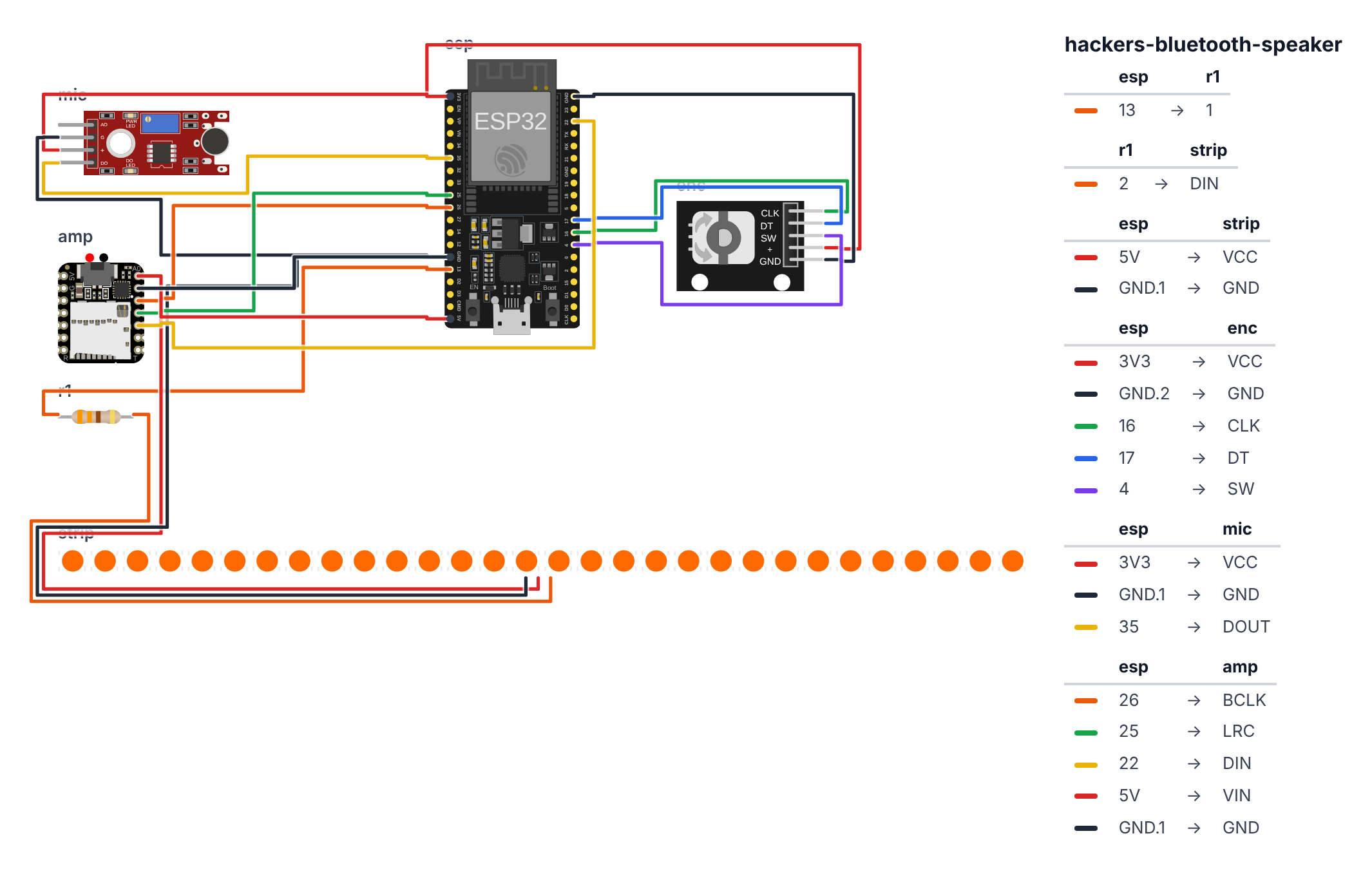
Step 1: Wire it up
Time: ~25 minutes
Classic ESP32 only: this build needs a classic ESP32 DevKit (ESP32-WROOM-32). Bluetooth music (A2DP) runs on Bluetooth Classic, and only the classic ESP32 has it. The ESP32-S3 and ESP32-C6 only have Bluetooth Low Energy (BLE), so if you pick them in the sketch it stops with a friendly error message. All pins below are for the classic ESP32.
PCM5102A I2S DAC (5 wires):
- PCM5102A BCK → GPIO 26
- PCM5102A LCK → GPIO 25
- PCM5102A DIN → GPIO 22
- PCM5102A VCC → 5V — red wire
- PCM5102A GND → GND — black wire
- PCM5102A FMT → GND (format select, per datasheet)
- PCM5102A SCK → GND (no MCLK needed)
PAM8403 Amplifier: 8. PAM8403 IN_L ← PCM5102A LOUT 9. PAM8403 IN_R ← PCM5102A ROUT 10. PAM8403 VCC → 5V 11. PAM8403 GND → GND 12. PAM8403 OUT_L+ / OUT_L- → Speaker L 13. PAM8403 OUT_R+ / OUT_R- → Speaker R
WS2812B LED Strip (3 wires): 14. LED DIN → GPIO 13 (via 330Ω resistor) 15. LED VCC → 5V 16. LED GND → GND
Rotary Encoder (5 wires): 17. Encoder CLK → GPIO 16 18. Encoder DT → GPIO 17 19. Encoder SW → GPIO 4 (push = loop mode toggle) 20. Encoder + → 3.3V 21. Encoder GND → GND
INMP441 Microphone (5 wires — power from 3.3V, NOT 5V): 22. INMP441 SCK → GPIO 32 23. INMP441 WS → GPIO 33 24. INMP441 SD → GPIO 35 (an input-only pin, which is fine: the mic sends data in) 25. INMP441 VDD → 3.3V — important: not 5V, this mic is 3.3V only 26. INMP441 GND → GND
Good to know: The wiring picture only draws the mic’s data wire (SD), because the simulator’s microphone has no SCK and WS pins. On your real board, connect all five wires listed above.
Check: PCM5102A FMT and SCK are pulled to GND. INMP441 is powered from 3.3V. Encoder SW is on GPIO 4.
Step 2: Install libraries and flash
Time: ~10 minutes
Install these libraries in Arduino IDE Library Manager:
- ESP32-A2DP by Phil Schatzmann — Bluetooth audio sink
- FastLED — WS2812B LED control
- arduinoFFT — frequency analysis
The big picture first. Your phone speaks to the ESP32 using Bluetooth A2DP — the same protocol every Bluetooth speaker uses. The ESP32 receives a stream of audio numbers and sends them down a wire (I2S) to a tiny chip called PCM5102A. That chip is a DAC — Digital-to-Analog Converter. It turns the numbers into real electrical wiggles, which the PAM8403 amplifier boosts loud enough to drive the speakers. While all that is happening, the ESP32 is also quietly peeking at those same audio numbers and running FFT math on them — splitting the sound into bass, mids, and highs — to decide which LEDs to light up. The encoder knob on the side talks to the ESP32 through an interrupt: every time you turn it, a tiny alarm fires and updates the volume number. The whole program is essentially three simultaneous jobs running in parallel: receive audio, light LEDs, watch the knob.
// ========== CHOOSE YOUR BOARD ==========
// Uncomment the line for YOUR board:
#define BOARD_ESP32  // classic ESP32 DevKit (ESP32-WROOM-32)
//#define BOARD_S3    // ESP32-S3-DevKitC-1
//#define BOARD_C6  // ESP32-C6-DevKitC-1
// ========================================

#ifdef BOARD_ESP32
  #define PIN_NEOPIXEL         13
  #define PIN_ENC_CLK          16
  #define PIN_ENC_DT           17
  #define PIN_ENC_SW           4
  #define PIN_I2S_BCK          26
  #define PIN_I2S_LRCK         25
  #define PIN_I2S_DOUT         22
  #define PIN_MIC_SCK          32
  #define PIN_MIC_WS           33
  #define PIN_MIC_SD           35
#endif
#ifdef BOARD_S3
  #error "Bluetooth speakers need a classic ESP32: the ESP32-S3 has no Bluetooth Classic (only BLE). Pick BOARD_ESP32 at the top."
#endif
#ifdef BOARD_C6
  #error "Bluetooth speakers need a classic ESP32: the ESP32-C6 has no Bluetooth Classic (only BLE). Pick BOARD_ESP32 at the top."
#endif

#include <FastLED.h>
#include "BluetoothA2DPSink.h"
#include <arduinoFFT.h>
#include <driver/i2s.h>

#define LED_PIN       PIN_NEOPIXEL
#define NUM_LEDS      30
#define ENC_CLK        PIN_ENC_CLK
#define ENC_DT         PIN_ENC_DT
#define ENC_SW         PIN_ENC_SW
#define I2S_BCK       PIN_I2S_BCK
#define I2S_LRCK      PIN_I2S_LRCK
#define I2S_DOUT      PIN_I2S_DOUT
#define MIC_SCK       PIN_MIC_SCK
#define MIC_WS        PIN_MIC_WS
#define MIC_SD        PIN_MIC_SD

CRGB leds[NUM_LEDS];

BluetoothA2DPSink a2dp_sink;

#define FFT_SAMPLES 64
double vReal[FFT_SAMPLES], vImag[FFT_SAMPLES];
ArduinoFFT<double> FFT(vReal, vImag, FFT_SAMPLES, 44100.0);

int volume = 80;

#define LOOP_BUF_SIZE 44100
int16_t loopBuffer[LOOP_BUF_SIZE];
int     loopWriteIdx  = 0;
bool    loopRecording = false;
bool    loopPlaying   = false;

volatile int encLastCLK;
void IRAM_ATTR encoderISR() {
  int clk = digitalRead(ENC_CLK);
  int dt  = digitalRead(ENC_DT);
  if (clk != encLastCLK && clk == 0) {
    if (dt != clk) volume = min(100, volume + 2);
    else           volume = max(0,   volume - 2);
    encLastCLK = clk;
  }
}

void audioDataCallback(const uint8_t* data, uint32_t len) {
  const int16_t* samples = (const int16_t*)data;
  int numSamples = len / 4;

  for (int i = 0; i < min(numSamples, FFT_SAMPLES); i++) {
    vReal[i] = samples[i * 2] * (volume / 100.0);
    vImag[i] = 0;
  }
}

void updateVisualizerLEDs() {
  FFT.windowing(FFTWindow::Hamming, FFTDirection::Forward);
  FFT.compute(FFTDirection::Forward);
  FFT.complexToMagnitude();

  float bass = 0, mids = 0, highs = 0;
  for (int i = 1; i <= 4;  i++) bass  += vReal[i];
  for (int i = 5; i <= 12; i++) mids  += vReal[i];
  for (int i = 13;i <= 32; i++) highs += vReal[i];

  bass  = constrain(bass  / 4.0f  / 5000.0f, 0.0f, 1.0f);
  mids  = constrain(mids  / 8.0f  / 3000.0f, 0.0f, 1.0f);
  highs = constrain(highs / 20.0f / 2000.0f, 0.0f, 1.0f);

  int bassLEDs  = (int)(bass  * 10);
  int midsLEDs  = (int)(mids  * 10);
  int highsLEDs = (int)(highs * 10);

  for (int i = 0; i < NUM_LEDS; i++) {
    float pos = (float)i / NUM_LEDS;
    if (pos < 0.33f) {
      leds[i] = (i < bassLEDs) ? CRGB(255, 20, 0) : CRGB(5, 0, 0);
    } else if (pos < 0.66f) {
      leds[i] = (i < 10 + midsLEDs) ? CRGB(0, 200, 20) : CRGB(0, 5, 0);
    } else {
      leds[i] = (i < 20 + highsLEDs) ? CRGB(20, 60, 255) : CRGB(0, 0, 5);
    }
  }
  FastLED.show();
}

void setup() {
  FastLED.addLeds<WS2812B, LED_PIN, GRB>(leds, NUM_LEDS);
  FastLED.setBrightness(80);

  pinMode(ENC_CLK, INPUT_PULLUP);
  pinMode(ENC_DT,  INPUT_PULLUP);
  pinMode(ENC_SW,  INPUT_PULLUP);
  encLastCLK = digitalRead(ENC_CLK);
  attachInterrupt(digitalPinToInterrupt(ENC_CLK), encoderISR, CHANGE);

  i2s_pin_config_t pin_config = {
    .bck_io_num   = I2S_BCK,
    .ws_io_num    = I2S_LRCK,
    .data_out_num = I2S_DOUT,
    .data_in_num  = I2S_PIN_NO_CHANGE
  };
  a2dp_sink.set_pin_config(pin_config);
  a2dp_sink.set_stream_reader(audioDataCallback, false);
  a2dp_sink.start("BuildCool Speaker");
}

void loop() {
  static bool lastSW = HIGH;
  static unsigned long pressStart = 0;
  bool sw = digitalRead(ENC_SW);
  if (sw == LOW && lastSW == HIGH) pressStart = millis();
  if (sw == LOW && (millis() - pressStart) > 500 && !loopRecording) {
    loopRecording = true;
    loopWriteIdx  = 0;
    loopPlaying   = false;
  }
  if (sw == HIGH && lastSW == LOW && loopRecording) {
    loopRecording = false;
    loopPlaying   = true;
  }
  lastSW = sw;

  updateVisualizerLEDs();

  delay(20);
}
Line-by-line: what every line does and why
Libraries and pin defines
#include <FastLED.h>
#include "BluetoothA2DPSink.h"
#include <arduinoFFT.h>
#include <driver/i2s.h>
Think of #include as opening a toolbox. FastLED is the LED toolbox. BluetoothA2DPSink is the Bluetooth music receiver toolbox — A2DP stands for Advanced Audio Distribution Profile, the standard every Bluetooth speaker in the world uses. arduinoFFT is the math toolbox that splits audio into bass/mids/highs. driver/i2s is the toolbox that handles the I2S digital audio wire going to the PCM5102A chip.
#define LED_PIN       PIN_NEOPIXEL
#define NUM_LEDS      30
#define ENC_CLK        PIN_ENC_CLK
#define ENC_DT         PIN_ENC_DT
#define ENC_SW         PIN_ENC_SW
#define I2S_BCK       PIN_I2S_BCK
#define I2S_LRCK      PIN_I2S_LRCK
#define I2S_DOUT      PIN_I2S_DOUT
#define is a nickname system. Wherever the code says LED_PIN, the compiler swaps it for PIN_NEOPIXEL — that is 13 on the classic ESP32. This means if you move a wire to a different pin, you only change one number in your board’s block at the top instead of hunting through the whole program.
Global variables: what the program remembers
BluetoothA2DPSink a2dp_sink;This creates the Bluetooth speaker object. Think of it as hiring a specialist assistant whose only job is receiving music from your phone. You give it instructions once in setup() and it works forever in the background.
#define FFT_SAMPLES 64
double vReal[FFT_SAMPLES], vImag[FFT_SAMPLES];
ArduinoFFT<double> FFT(vReal, vImag, FFT_SAMPLES, 44100.0);
vReal and vImag are two shelves of 64 numbers each. When FFT math runs, it needs both. vReal holds the actual audio samples. vImag starts at all zeros (we are not doing complex signal processing — only one-dimensional audio). ArduinoFFT is the calculator that will use both shelves.
int volume = 80;Volume stored as a number from 0 (silent) to 100 (full). Starts at 80 so you hear something immediately. The encoder knob changes this number.
#define LOOP_BUF_SIZE 44100
int16_t loopBuffer[LOOP_BUF_SIZE];
int     loopWriteIdx  = 0;
bool    loopRecording = false;
bool    loopPlaying   = false;
This is the loop feature’s memory. loopBuffer is a shelf of 44100 numbers — one second of audio (44,100 samples per second). int16_t means each number is a 16-bit integer, which is standard audio quality. loopWriteIdx is the bookmark: which slot to write into next. loopRecording and loopPlaying are on/off switches for the two modes.
encoderISR — the volume knob interrupt
volatile int encLastCLK;
void IRAM_ATTR encoderISR() {
  int clk = digitalRead(ENC_CLK);
  int dt  = digitalRead(ENC_DT);
  if (clk != encLastCLK && clk == 0) {
    if (dt != clk) volume = min(100, volume + 2);
    else           volume = max(0,   volume - 2);
    encLastCLK = clk;
  }
}
volatile means “this variable can change at any moment from outside the normal code flow — never cache it, always read fresh from memory.” The encoder’s physical pins flicker as you turn the knob; the CPU must always read the real current value, not a saved copy.
IRAM_ATTR tells the compiler to store this function in a special always-awake section of RAM called IRAM. Normal code lives in flash memory, which can take a microsecond to fetch. Interrupts need to run in nanoseconds, so IRAM_ATTR keeps this function in fast-access RAM — like keeping your fire extinguisher on the wall, not in a locked cupboard.
When the knob turns, CLK and DT pins change in a specific order. If dt != clk, the knob turned clockwise → volume goes up by 2 (but never above 100). Otherwise counterclockwise → volume goes down (but never below 0). min() and max() are the safety rails.
audioDataCallback — music arriving from your phone
void audioDataCallback(const uint8_t* data, uint32_t len) {
  const int16_t* samples = (const int16_t*)data;
  int numSamples = len / 4;

  for (int i = 0; i < min(numSamples, FFT_SAMPLES); i++) {
    vReal[i] = samples[i * 2] * (volume / 100.0);
    vImag[i] = 0;
  }
}
This function is called automatically by the A2DP library whenever your phone sends a new chunk of music. Think of it as a mail slot — whenever a letter arrives, this function runs.
data is the raw bytes of stereo audio. The format is interleaved: Left, Right, Left, Right… — 2 bytes per channel = 4 bytes per stereo “frame.” len / 4 gives us the number of stereo frames. samples[i * 2] picks only the left channel (every second sample starting at index 0). Multiplying by (volume / 100.0) scales the signal: at volume 80, each sample becomes 80% of its original size. This is how digital volume control works — just multiplication.
updateVisualizerLEDs — splitting sound into bass, mids, highs
void updateVisualizerLEDs() {
  FFT.windowing(FFTWindow::Hamming, FFTDirection::Forward);
  FFT.compute(FFTDirection::Forward);
  FFT.complexToMagnitude();
Three steps of FFT math. windowing applies a mathematical envelope to the 64 samples before analysis — this prevents a problem called spectral leakage (imagine cutting a recording in the middle of a note; the sharp cut creates false high frequencies). compute does the actual FFT calculation. complexToMagnitude converts the result from complex numbers into simple loudness values per frequency band.
  float bass = 0, mids = 0, highs = 0;
  for (int i = 1; i <= 4;  i++) bass  += vReal[i];
  for (int i = 5; i <= 12; i++) mids  += vReal[i];
  for (int i = 13;i <= 32; i++) highs += vReal[i];
After FFT, vReal[1] through vReal[32] each hold the loudness of a different frequency range. Bins 1–4 are low frequencies (bass: kick drum, bass guitar). Bins 5–12 are mid frequencies (vocals, guitar). Bins 13–32 are high frequencies (hi-hats, cymbals). Adding the bins in each group gives a total loudness for that range.
  bass  = constrain(bass  / 4.0f  / 5000.0f, 0.0f, 1.0f);
  mids  = constrain(mids  / 8.0f  / 3000.0f, 0.0f, 1.0f);
  highs = constrain(highs / 20.0f / 2000.0f, 0.0f, 1.0f);
The raw FFT numbers can be in the thousands. Dividing by the number of bins (4, 8, 20) gives the average. Dividing by the scale value (5000, 3000, 2000) shrinks everything into the 0.0–1.0 range. constrain clamps the result so it never goes below 0 or above 1 — like a safety fence.
  int bassLEDs  = (int)(bass  * 10);
  int midsLEDs  = (int)(mids  * 10);
  int highsLEDs = (int)(highs * 10);
The strip has 30 LEDs divided into three zones of 10 each. Multiplying the 0–1 loudness by 10 gives how many LEDs in that zone should light up. Loud bass → bassLEDs = 10 (all 10 bass LEDs on). Quiet bass → bassLEDs = 2 (only 2 lit).
  for (int i = 0; i < NUM_LEDS; i++) {
    float pos = (float)i / NUM_LEDS;
    if (pos < 0.33f) {
      leds[i] = (i < bassLEDs) ? CRGB(255, 20, 0) : CRGB(5, 0, 0);
    } else if (pos < 0.66f) {
      leds[i] = (i < 10 + midsLEDs) ? CRGB(0, 200, 20) : CRGB(0, 5, 0);
    } else {
      leds[i] = (i < 20 + highsLEDs) ? CRGB(20, 60, 255) : CRGB(0, 0, 5);
    }
  }
  FastLED.show();
For every LED, pos is its fraction along the strip (0.0 at start, 1.0 at end). The first third gets bass colors — bright orange-red CRGB(255, 20, 0) when lit, dim dark red CRGB(5, 0, 0) when not. The ? symbol is a shortcut: (condition) ? valueIfTrue : valueIfFalse. FastLED.show() sends all 30 color values down the single wire to the LEDs.
setup — starting everything up
  a2dp_sink.set_pin_config(pin_config);
  a2dp_sink.set_stream_reader(audioDataCallback, false);
  a2dp_sink.start("BuildCool Speaker");
These three lines configure the Bluetooth speaker. set_pin_config tells the library which GPIO pins carry the I2S digital audio signal to the PCM5102A chip. set_stream_reader registers the callback function — it tells the library “whenever music arrives, call audioDataCallback.” start("BuildCool Speaker") broadcasts this name over Bluetooth. This is the name that appears on your phone when you search for speakers.
loop — the loop mode button logic
  if (sw == LOW && lastSW == HIGH) pressStart = millis();
  if (sw == LOW && (millis() - pressStart) > 500 && !loopRecording) {
    loopRecording = true;
    loopWriteIdx  = 0;
    loopPlaying   = false;
  }
  if (sw == HIGH && lastSW == LOW && loopRecording) {
    loopRecording = false;
    loopPlaying   = true;
  }
millis() returns how many milliseconds have passed since the ESP32 powered on — like a stopwatch. When the button first goes LOW (pressed), pressStart records the timestamp. Every loop, the second if checks: is the button still held down AND has 500 milliseconds passed? If yes, start recording. When the button is released (goes HIGH again) while recording was active, switch to playback mode. This is a hold-to-activate pattern — a brief accidental touch does nothing, only a deliberate half-second hold triggers it.
The whole thing in one sentence
Your phone streams music over Bluetooth → the ESP32 passes it to the PCM5102A chip to play through speakers → simultaneously grabs the audio data, runs FFT math on it, and lights up 30 LEDs in three colored zones matching bass, mids, and highs → while a knob interrupt silently keeps the volume number updated at all times.
First thing to try: After uploading, open Bluetooth on your phone, find “BuildCool Speaker,” connect, and play a song with a strong bass beat. Watch the first third of the LED strip pulse red with each kick drum hit.
Check: After upload, open Bluetooth on your phone. You should see “BuildCool Speaker” in the available devices list.
Step 3: Connect and configure
Time: ~3 minutes
- Open Bluetooth settings on your phone
- Pair to “BuildCool Speaker” — it appears as a standard Bluetooth audio device
- Play any music — the LEDs should immediately react
- Turn the encoder knob to adjust volume
Tune the LED sensitivity: The scale values (5000.0f, 3000.0f, 2000.0f) in updateVisualizerLEDs() affect how sensitive each band is. If bass LEDs never light up, decrease the bass scale. If they’re always maxed out, increase it. Tune by ear until the visualization feels right for the music you play.
Step 4: Use it!
Bluetooth pairing: Once paired, your phone reconnects automatically next time. Play music, listen on your homemade speaker.
Watch the visualizer: Bass frequencies — kick drums, bass guitar, sub — pulse in the first third of the strip (red). Vocals and guitar bloom in the middle third (green). Hi-hats and air frequencies shimmer across the whole strip (blue).
Activate loop mode: Hold the encoder button for half a second until the LEDs change behavior. The speaker is now recording from the microphone. Release to play the loop back on repeat — the same trick the $599 OB-4 does.
Mount it: The frosted acrylic slot aesthetic: cut a piece of 3mm frosted acrylic to 200mm × 15mm, mount the LED strip behind it flush against the speaker enclosure. The frosted surface diffuses individual LEDs into a smooth, glowing band.
What just happened (what you learned)
-
Bluetooth A2DP (Advanced Audio Distribution Profile) — the protocol your phone uses to send music wirelessly. It’s “Bluetooth Classic” — different from BLE. That’s why this build needs the classic ESP32: the S3 and C6 only speak BLE. A2DP compresses music with SBC codec, sends it over Bluetooth, and the ESP32 decodes it back into raw audio samples.
-
PCM5102A — a dedicated 24-bit DAC chip. “24-bit” means 16 million possible sample levels instead of 256 (8-bit) or 65,536 (16-bit). The difference is dynamic range — loud parts stay loud, quiet parts stay audible. Professional audio uses 24-bit; the ESP32’s built-in DAC is 8-bit.
-
FFT (Fast Fourier Transform) — turns a list of audio samples (just numbers) into a frequency spectrum. Your brain does something similar when it listens to music and hears “bass” vs “treble” as separate things. The ESP32 does it 50 times per second, which is why the LEDs dance in real time.
-
Class D amplifier (PAM8403) — switches output transistors on and off very fast (hundreds of kHz) instead of linearly controlling current. “Class D” sounds bad but it’s extremely efficient: 90%+ power efficiency. No heatsink needed because almost no power becomes heat.
Level Up
Implement proper volume control. The current code stores volume but uses it only for FFT scaling. Multiply every audio sample by volume/100.0f before it reaches I2S output. What happens at volume 0? At 200%? (Clipping — numbers overflow. This teaches audio headroom.)
Complete the loop buffer. loopPlaying = true is set, but there’s no playback code. Write a task that reads from loopBuffer in a loop and sends it to I2S output, handling the read index wrapping at LOOP_BUF_SIZE. That’s the OB-4’s signature feature — build it yourself.
Change LED zones. Try: all 30 LEDs show volume of a single frequency band — a VU meter that bounces left-right with the beat. Or: interleaved — even LEDs = bass, odd LEDs = highs.
★★ You completed: Bluetooth Speaker!
Troubleshooting
| Problem | Fix |
|---|---|
| Phone can’t find the speaker | Make sure it’s a classic ESP32 (ESP32-WROOM-32) — an S3 or C6 can’t do Bluetooth Classic. Check ESP32 is powered on and has A2DP library installed. Try restarting both. “BuildCool Speaker” appears in Bluetooth scan — not as a BLE device. |
| No sound from speakers | Check PCM5102A to PAM8403 wiring (LOUT/ROUT to IN_L/IN_R). Check speaker polarity. Check 5V power to both chips. |
| LEDs don’t react to music | Check DIN on GPIO 13 with 330Ω resistor. The FFT callback fires only when audio is actually streaming — make sure music is playing on your phone. |
| INMP441 mic doesn’t work | Check it’s powered from 3.3V (not 5V). Check SCK/WS/SD wiring. |
| Volume encoder does nothing | Check CLK on GPIO 16, DT on GPIO 17. The encoder ISR only fires if those interrupts are attached correctly. |
| Speaker hums or buzzes | Check all GND connections are tied to a common ground. The PAM8403 needs a clean ground shared with the PCM5102A. |