Parent info
Parts you need
Affiliate links — we may earn a small commission
Try this circuit in your browser!
Run the code, press the buttons and watch what happens — before you buy any parts. No account needed.
Open in Simulator →You hang it on your wall. It comes alive with your music.
Imagine this: a glowing panel on your bedroom wall, mounted behind a square of frosted acrylic. Music plays — 64 LEDs dance in a spectrum analyzer pattern, green bars rising and falling with each beat. You press a button — the panel transforms into a roaring fire animation, orange and yellow tongues flickering upward from a heat simulation running in pure math. Press again — cascading green characters fall like digital rain.
Visitors will ask where you bought it. You say: I built it.
Nanoleaf charges $200 for something less capable. Yours costs $20.
What you’ll need
| Part | What it does | Price |
|---|---|---|
| ESP32-S3-DevKitC-1 | Brain. Runs FFT and animation simultaneously. | ~$8 |
| WS2812B 8×8 LED matrix (64 LEDs) | 64 individually addressable LEDs arranged in a grid. | ~$6 |
| INMP441 MEMS microphone | Captures live audio for spectrum analyzer mode. Powered at 3.3V only. | ~$3 |
| Frosted acrylic 120mm × 120mm | Diffuser panel — transforms 64 individual dots into a smooth glowing surface. | ~$2 |
| Push button | Cycles through display modes. | ~$1 |
Total: ~$20 | Time: ~2.5 hours | Difficulty: ●●●○○
Power note: 64 WS2812B LEDs at full white draw about 3.8A at 5V = 19W. Use a dedicated 5V 2A adapter — do NOT run from a USB port alone. Typical mixed-color operation at 60–80% brightness draws closer to 1.5A.
How it works (60 seconds)
Think of the LED matrix as a tiny TV screen — 8×8 pixels, each controllable independently.
In spectrum analyzer mode: the INMP441 mic captures ambient audio. FFT math splits the sound into 8 frequency bands. Each band maps to one column of LEDs — the bar height shows how loud that frequency is right now. Update 25 times per second and you have a dancing equalizer display.
In fire mode: no mic needed. A cellular automaton algorithm runs on the grid — each LED’s “heat” is calculated from its neighbors. Random values at the bottom (the “fuel”), heat diffusing upward, cooling as it rises. Simple math, complex emergent behavior: real-looking fire.
The frosted acrylic diffuser in front turns 64 individual LED dots into overlapping blobs of light — that’s the entire Nanoleaf aesthetic, achievable for $2 of acrylic.
Step 0: Understand serpentine wiring
Time: ~5 minutes
Pre-built 8×8 WS2812B matrices wire LEDs in a snake pattern to minimize wire length:
- Row 0: LED 0→7 (left to right)
- Row 1: LED 8→15 (RIGHT to left)
- Row 2: LED 16→23 (left to right)
- …alternating
This means drawing a vertical line by naively writing to row * 8 + col produces a diagonal zigzag. The xy(x, y) function in the code handles this translation automatically. Always use xy(col, row) to address LEDs by 2D coordinates.
Step 1: Wire it up
Time: ~15 minutes
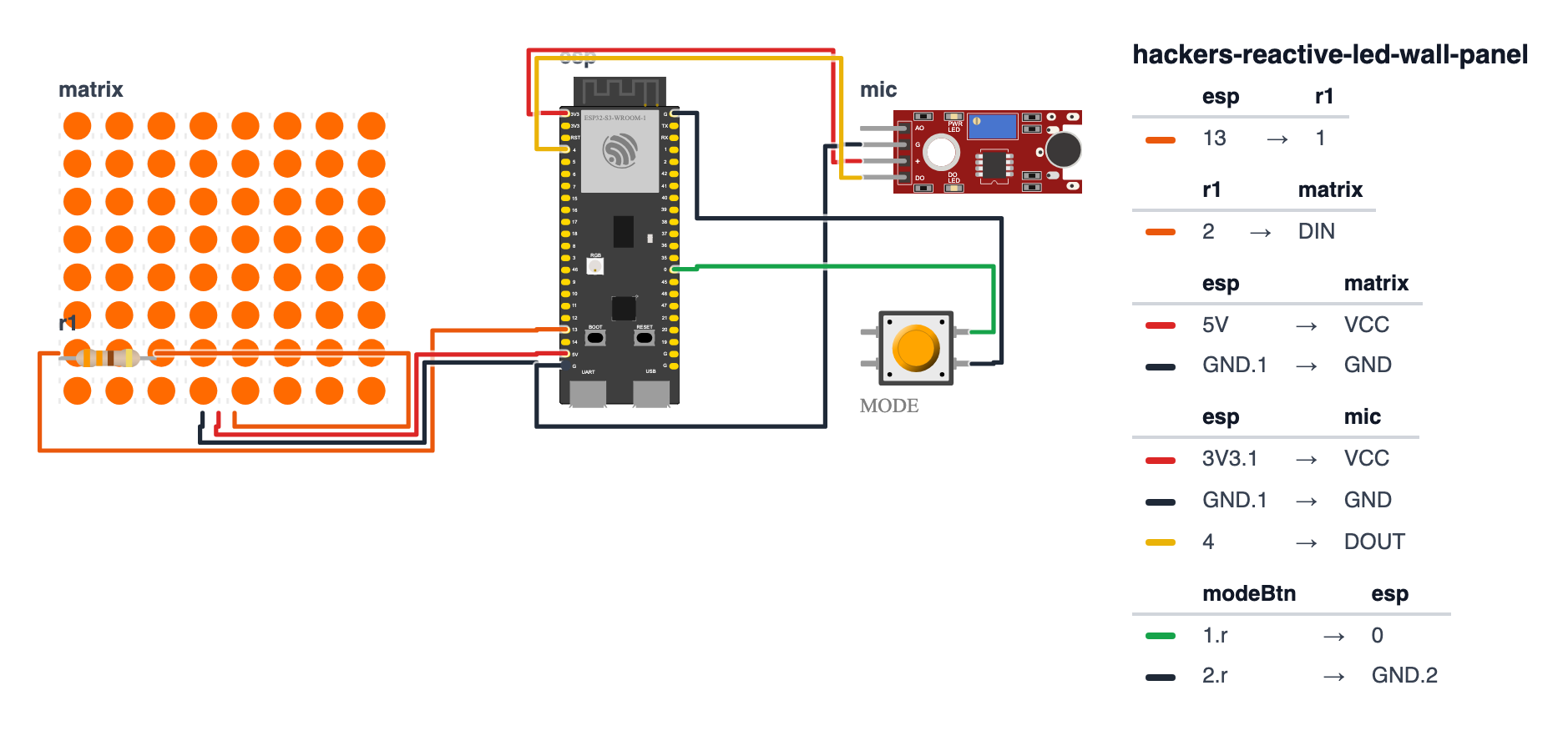
INMP441 Microphone (5 wires — 3.3V only):
- INMP441 SCK → GPIO 4
- INMP441 WS → GPIO 5
- INMP441 SD → GPIO 6
- INMP441 VDD → 3.3V — not 5V
- INMP441 GND → GND
- INMP441 L/R → GND
WS2812B 8×8 LED Matrix (3 wires): 7. Matrix DIN → 330Ω → GPIO 13 8. Matrix VCC → 5V from dedicated 2A supply 9. Matrix GND → GND
Mode Button (2 wires): 10. Button → GPIO 0 | other leg → GND
Check: INMP441 on 3.3V. Matrix on 5V from a real supply (not board’s 5V pin for full brightness). 330Ω resistor on data line.
Step 2: Flash the code
Time: ~15 minutes
Install in Arduino IDE Library Manager:
- FastLED — LED matrix control
- arduinoFFT — frequency analysis
The big picture first. The LED matrix is like a tiny 8×8 screen — 64 individually controllable pixels arranged in a grid. The xy(x, y) function is the translator between “draw something at column 3, row 5” and “which LED number in the chain is that?” — necessary because pre-built matrices wire their LEDs in a snake pattern, not a neat grid. In spectrum mode, the microphone captures sound, FFT math splits it into 8 frequency bands, and each band controls one column of LEDs like an equalizer bar. In fire mode, there is no microphone — instead, a cellular automaton runs on the grid: each LED has a “heat” value, and every frame it gets recalculated from its neighbors with a slight cooling effect. The emergent result looks exactly like real fire even though it is just averaging numbers and subtracting three. The mode button cycles through six display modes — its interrupt sets a flag, and the main loop checks that flag instead of checking the button directly. This keeps the button response instant even during slow animation drawing.
// ========== CHOOSE YOUR BOARD ==========
// Uncomment the line for YOUR board:
#define BOARD_S3    // ESP32-S3-DevKitC-1
//#define BOARD_C6  // ESP32-C6-DevKitC-1
// ========================================

#ifdef BOARD_S3
  #define PIN_NEOPIXEL         13
  #define PIN_MODE_BTN         0
  #define PIN_MIC_SCK          4
  #define PIN_MIC_WS           5
  #define PIN_MIC_SD           6
#endif
#ifdef BOARD_C6
  #define PIN_NEOPIXEL         5
  #define PIN_MODE_BTN         9
  #define PIN_MIC_SCK          0
  #define PIN_MIC_WS           19
  #define PIN_MIC_SD           20
#endif

#include <FastLED.h>
#include <driver/i2s.h>
#include <arduinoFFT.h>

#define LED_PIN      PIN_NEOPIXEL
#define MATRIX_W      8
#define MATRIX_H      8
#define NUM_LEDS     (MATRIX_W * MATRIX_H)
#define MODE_BTN      PIN_MODE_BTN
#define MIC_SCK       PIN_MIC_SCK
#define MIC_WS        PIN_MIC_WS
#define MIC_SD        PIN_MIC_SD
#define FFT_SAMPLES  64
#define SAMPLE_RATE  44100

CRGB leds[NUM_LEDS];

int xy(int x, int y) {
  x = constrain(x, 0, MATRIX_W - 1);
  y = constrain(y, 0, MATRIX_H - 1);
  if (y % 2 == 0) return y * MATRIX_W + x;
  else            return y * MATRIX_W + (MATRIX_W - 1 - x);
}

enum Mode { SPECTRUM, WAVEFORM, FIRE, RAIN, PULSE, MATRIX_RAIN };
Mode currentMode = SPECTRUM;
volatile bool modeBtnPressed = false;
void IRAM_ATTR modeBtnISR() { modeBtnPressed = true; }

double vReal[FFT_SAMPLES], vImag[FFT_SAMPLES];
ArduinoFFT<double> FFT(vReal, vImag, FFT_SAMPLES, SAMPLE_RATE);

uint8_t fire[MATRIX_W][MATRIX_H + 2];

void readMic() {
  int32_t buf[FFT_SAMPLES];
  size_t bytesRead;
  i2s_read(I2S_NUM_0, buf, sizeof(buf), &bytesRead, 10);
  for (int i = 0; i < FFT_SAMPLES; i++) {
    vReal[i] = (double)(buf[i] >> 8);
    vImag[i] = 0;
  }
}

void drawSpectrum() {
  readMic();
  FFT.windowing(FFTWindow::Hamming, FFTDirection::Forward);
  FFT.compute(FFTDirection::Forward);
  FFT.complexToMagnitude();

  fill_solid(leds, NUM_LEDS, CRGB::Black);

  for (int col = 0; col < MATRIX_W; col++) {
    int startBin = 1 + col * 3;
    float magnitude = 0;
    for (int b = startBin; b < startBin + 3; b++) {
      if (b < FFT_SAMPLES / 2) magnitude += vReal[b];
    }
    int barH = constrain((int)(magnitude / 600000.0f * MATRIX_H), 0, MATRIX_H);

    for (int row = 0; row < barH; row++) {
      uint8_t hue = map(row, 0, MATRIX_H, 96, 0);
      leds[xy(col, MATRIX_H - 1 - row)] = CHSV(hue, 255, 200);
    }
  }
  FastLED.show();
}

void drawFire() {
  for (int x = 0; x < MATRIX_W; x++) {
    fire[x][MATRIX_H + 1] = random8(180, 255);
    fire[x][MATRIX_H]     = random8(160, 240);
  }

  for (int y = 0; y < MATRIX_H; y++) {
    for (int x = 0; x < MATRIX_W; x++) {
      int total = fire[(x-1+MATRIX_W)%MATRIX_W][y+1]
                + fire[x][y+1]
                + fire[(x+1)%MATRIX_W][y+1]
                + fire[x][(y+2 <= MATRIX_H+1) ? y+2 : y+1];
      fire[x][y] = (total / 4) > 3 ? (total / 4) - 3 : 0;
    }
  }

  for (int x = 0; x < MATRIX_W; x++) {
    for (int y = 0; y < MATRIX_H; y++) {
      uint8_t heat = fire[x][y];
      CRGB color;
      if (heat < 85)       color = CRGB(heat * 3, 0, 0);
      else if (heat < 170) color = CRGB(255, (heat-85)*3, 0);
      else                 color = CRGB(255, 255, (heat-170)*3);
      leds[xy(x, MATRIX_H - 1 - y)] = color;
    }
  }
  FastLED.show();
  delay(40);
}

void setup() {
  FastLED.addLeds<WS2812B, LED_PIN, GRB>(leds, NUM_LEDS);
  FastLED.setBrightness(80);

  pinMode(MODE_BTN, INPUT_PULLUP);
  attachInterrupt(digitalPinToInterrupt(MODE_BTN), modeBtnISR, FALLING);

  i2s_config_t cfg = {
    .mode              = (i2s_mode_t)(I2S_MODE_MASTER | I2S_MODE_RX),
    .sample_rate       = SAMPLE_RATE,
    .bits_per_sample   = I2S_BITS_PER_SAMPLE_32BIT,
    .channel_format    = I2S_CHANNEL_FMT_ONLY_LEFT,
    .communication_format = I2S_COMM_FORMAT_STAND_I2S,
    .intr_alloc_flags  = ESP_INTR_FLAG_LEVEL1,
    .dma_buf_count     = 4,
    .dma_buf_len       = FFT_SAMPLES,
  };
  i2s_pin_config_t pins = {
    .bck_io_num   = MIC_SCK,
    .ws_io_num    = MIC_WS,
    .data_out_num = I2S_PIN_NO_CHANGE,
    .data_in_num  = MIC_SD
  };
  i2s_driver_install(I2S_NUM_0, &cfg, 0, NULL);
  i2s_set_pin(I2S_NUM_0, &pins);
}

void loop() {
  if (modeBtnPressed) {
    currentMode = (Mode)((currentMode + 1) % 6);
    modeBtnPressed = false;
    fill_solid(leds, NUM_LEDS, CRGB::Black);
  }

  switch (currentMode) {
    case SPECTRUM:   drawSpectrum(); break;
    case FIRE:       drawFire();     break;
    default:         drawSpectrum(); break;
  }
}
Line-by-line: what every line does and why
The xy() function — solving the serpentine puzzle
int xy(int x, int y) {
  x = constrain(x, 0, MATRIX_W - 1);
  y = constrain(y, 0, MATRIX_H - 1);
  if (y % 2 == 0) return y * MATRIX_W + x;
  else            return y * MATRIX_W + (MATRIX_W - 1 - x);
}
Pre-built 8×8 LED matrices wire their LEDs in a snake pattern to minimize wire length. Row 0 goes left-to-right (LED 0 to 7). Row 1 goes right-to-left (LED 8 to 15). Row 2 goes left-to-right again. This zigzag is called serpentine wiring. Without xy(), if you tried to draw a vertical line by writing to column 3 of every row, it would zigzag diagonally across the panel.
constrain is a safety fence — x and y cannot go below 0 or above 7. If you accidentally ask for column 10 of an 8-wide matrix, constrain clips it to 7 instead of crashing.
y % 2 == 0 checks if the row number is even (0, 2, 4, 6). Even rows go left-to-right, so LED number = row × 8 + column. Odd rows go right-to-left, so LED number = row × 8 + (7 - column). Subtracting the column from 7 flips the direction.
enum Mode — the six display modes
enum Mode { SPECTRUM, WAVEFORM, FIRE, RAIN, PULSE, MATRIX_RAIN };
Mode currentMode = SPECTRUM;
enum creates a list of named states. The compiler stores them as numbers (SPECTRUM=0, WAVEFORM=1, FIRE=2…) but you read the meaningful names. When the button is pressed:
currentMode = (Mode)((currentMode + 1) % 6);This cycles through the modes. % 6 wraps back to 0 after MATRIX_RAIN (mode 5). The (Mode) cast converts the number back to the enum type. Think of it like a rotary switch that clicks through six positions and then wraps back to the first.
modeBtnISR — the button interrupt flag
volatile bool modeBtnPressed = false;
void IRAM_ATTR modeBtnISR() { modeBtnPressed = true; }
The interrupt does only one thing: set a flag to true. The actual mode change happens in the main loop when it checks this flag. Why this pattern? Drawing drawFire() can take 40+ milliseconds. If the interrupt tried to change modes while drawing was happening, it could corrupt the LED array mid-frame. By only setting a flag in the interrupt and acting on it in the main loop between frames, the mode change always happens at a safe moment.
volatile means “this variable can change at any moment from the interrupt — never use a stale cached copy, always read fresh from memory.”
drawSpectrum — the equalizer display
  for (int col = 0; col < MATRIX_W; col++) {
    int startBin = 1 + col * 3;
    float magnitude = 0;
    for (int b = startBin; b < startBin + 3; b++) {
      if (b < FFT_SAMPLES / 2) magnitude += vReal[b];
    }
    int barH = constrain((int)(magnitude / 600000.0f * MATRIX_H), 0, MATRIX_H);
After FFT, vReal[1] through vReal[32] each hold the loudness of a different frequency slice. Column 0 uses bins 1–3 (lowest bass). Column 1 uses bins 4–6. Column 7 uses bins 22–24 (highest treble). Each column averages 3 adjacent bins, giving 8 frequency bands across the 8 columns. Dividing by 600,000 scales the raw FFT numbers (which can be in the millions) down to 0.0–1.0. Multiplying by MATRIX_H (8) gives how many LEDs tall the bar should be.
      uint8_t hue = map(row, 0, MATRIX_H, 96, 0);
      leds[xy(col, MATRIX_H - 1 - row)] = CHSV(hue, 255, 200);
map(row, 0, 8, 96, 0) converts the row number to a hue value. Hue 96 is green (at the bottom). Hue 0 is red (at the top). So tall bars are red at the peak and green at the base — exactly like a professional equalizer display. MATRIX_H - 1 - row flips the drawing direction so bars grow upward from the bottom (row 7) rather than downward from the top.
drawFire — the cellular automaton
  for (int x = 0; x < MATRIX_W; x++) {
    fire[x][MATRIX_H + 1] = random8(180, 255);
    fire[x][MATRIX_H]     = random8(160, 240);
  }
The fire array is two rows taller than the visible grid — these hidden bottom rows are the “fuel source.” Every frame, they get refilled with random high heat values (180–255 out of 255). The randomness is what makes the fire flicker rather than burn uniformly.
  for (int y = 0; y < MATRIX_H; y++) {
    for (int x = 0; x < MATRIX_W; x++) {
      int total = fire[(x-1+MATRIX_W)%MATRIX_W][y+1]
                + fire[x][y+1]
                + fire[(x+1)%MATRIX_W][y+1]
                + fire[x][(y+2 <= MATRIX_H+1) ? y+2 : y+1];
      fire[x][y] = (total / 4) > 3 ? (total / 4) - 3 : 0;
    }
  }
Each cell’s new heat = average of the three cells below it plus one cell two rows down, minus 3. Dividing by 4 averages them. Subtracting 3 is the cooling — heat dissipates as it rises. The %MATRIX_W wrapping on x makes the fire wrap around horizontally (left edge and right edge are neighbors), which prevents cold vertical stripes at the edges.
      if (heat < 85)       color = CRGB(heat * 3, 0, 0);
      else if (heat < 170) color = CRGB(255, (heat-85)*3, 0);
      else                 color = CRGB(255, 255, (heat-170)*3);
Heat 0–84: dark red (cold embers), multiplied by 3 to fill 0–255. Heat 85–169: full red plus growing green = orange-yellow. Heat 170–255: full red, full green, growing blue = near-white hot core. These three color bands create the classic fire color gradient from ember-red through orange-yellow to white-hot center.
The whole thing in one sentence
Press the button to cycle through modes — in spectrum mode the microphone feeds FFT data to 8 equalizer columns on the grid, in fire mode a cellular automaton simulates heat diffusing upward from randomly seeded fuel, and the xy() function translates your intuitive 2D coordinates into the correct LED numbers for the serpentine-wired matrix.
First thing to try: Upload, play music near the microphone in spectrum mode — you should see 8 green columns rise and fall like a real equalizer. Press the button once to switch to fire mode — watch the flames appear in a dark room with the diffuser acrylic in front.
Check: After upload, play music near the mic — the top rows should light up in the spectrum analyzer mode. Press the mode button to switch to fire.
Step 3: Build the diffuser panel
Time: ~10 minutes
The frosted acrylic is what makes this look like a Nanoleaf panel instead of a bare LED matrix.
- Cut 3mm frosted acrylic to exactly 100mm × 100mm (to fit the 8×8 matrix)
- Mount the LED matrix on 10–15mm standoffs (small plastic spacers)
- Place the frosted acrylic in front — the gap between acrylic and LEDs controls diffusion. More gap = smoother blend. 15mm is ideal.
- Mount on wall with two 3M Command strips on the acrylic panel back. Run a single USB power cable down behind a picture frame.
The diffusion turns 64 individual LED pixels into overlapping blobs of light — that’s the entire visual effect.
Step 4: Use all 6 modes
Press the mode button to cycle through modes. Each press advances to the next:
SPECTRUM — 8-column spectrum analyzer. Each column = a frequency band. Green at base, red at peaks. Put on music and watch it respond.
WAVEFORM (extend this yourself) — raw audio waveform scrolling across the panel like an oscilloscope. The code placeholder calls drawSpectrum() — replace with your own oscilloscope display.
FIRE — cellular automaton fire. No audio needed. Watch the math create irregular, organic flames. Looks best in a dim room.
RAIN (extend this yourself) — green drops cascade from top. The struct is defined in the code — add the animation logic.
PULSE (extend this yourself) — whole panel throbs with the beat.
MATRIX_RAIN (extend this yourself) — cascading characters in classic green.
What just happened (what you learned)
-
Cellular Automaton — the algorithm behind the fire effect. Each cell (LED) in the grid has a state (heat value). On each frame, every cell’s new state is calculated from its neighbors’ current states using a simple rule: average lower neighbors, subtract 3. The behavior that emerges is complex and organic — irregular flickering flames from pure math. Conway’s Game of Life uses the same principle.
-
Serpentine wiring — used in pre-built LED matrices to minimize total wire length. The
xy()function is pure coordinate translation — math that makes intuitive 2D code work on physical hardware wired in a snake pattern. -
HSV color model — in RGB, to change from green to red you increase R while decreasing G. In HSV (Hue, Saturation, Value), you just change H from 120 (green) to 0 (red). The spectrum analyzer uses
CHSV(hue, 255, 200)to transition through colors naturally. -
Power budget — 64 WS2812B LEDs at full white draw 3.8A at 5V = 19W. Running from a USB port (0.5A max) would overheat the cable and damage the port. A dedicated 5V 2A adapter handles typical mixed content safely.
Level Up
Complete WAVEFORM mode. Instead of FFT, read raw mic samples and draw them as a scrolling horizontal line. The y-position of each column = the audio amplitude. Scroll left each frame as new samples arrive — this is what an oscilloscope shows.
Implement RAIN mode. Start 8 drops at the top, each at a random column. Each frame: draw the drop head in bright green, trailing cells in fading green. When a drop reaches bottom, reset to top. The rainDrops[8] struct is already defined in the code.
Upgrade to 16×16. Change MATRIX_W and MATRIX_H to 16. Buy a 256-LED matrix (~$15). All code adapts automatically. Power requirement jumps to ~15A at 5V — you’ll need a dedicated supply. The visual impact is dramatically better.
★★ You completed: Reactive LED Wall Panel!
Troubleshooting
| Problem | Fix |
|---|---|
| LEDs don’t light up at all | Check 5V supply is connected and rated 2A+. Check DIN wiring with 330Ω resistor. Check GND is shared between matrix and ESP32. |
| Wrong LEDs light up | Serpentine mapping mismatch. Check if your matrix starts L→R or R→L on row 0. Invert: if (y % 2 == 1) vs if (y % 2 == 0) in xy(). |
| Spectrum doesn’t react to music | Check INMP441 wiring: SCK→4, WS→5, SD→6, VDD→3.3V. Try clapping loudly near the mic. Tune scale value in drawSpectrum(). |
| Fire effect is too uniform | The randomness needs esp_random() to be truly random. Check that random8() from FastLED is working (requires FastLED initialized). |
| Button doesn’t change mode | GPIO 0 has a special meaning on some boards (boot button). Try a different GPIO. Check attachInterrupt in setup(). |
| LEDs overheat / smell burning | Running at too high brightness from USB power. Use dedicated 5V supply. Set FastLED.setBrightness(60) or lower. |