Parent info
Parts you need
Affiliate links — we may earn a small commission
Try this circuit in your browser!
Run the code, press the buttons and watch what happens — before you buy any parts. No account needed.
Open in Simulator →You press a button. A light turns on. Your beat plays forever.
Imagine this: a 4×4 grid of buttons sitting on your desk. You press button 1 — a red LED lights up. Press button 5 — another lights up. Press button 9 and 13. Hit Play. A kick drum pounds out exactly the beat you just programmed, the LEDs sweeping across as it plays.
That’s a drum machine. The Roland TR-808 invented this pattern in 1980 and every beat machine since uses the same idea. You’re building the core of it for $25.
What you’ll need
| Part | What it does | Price |
|---|---|---|
| ESP32-S3 Dev Board | Brain. Runs the sequencer and drives audio. | ~$12 |
| 4×4 button matrix (16 buttons) | 16 sequencer steps — one button per step. | ~$2 |
| MAX98357A I2S Amplifier | Digital audio signal → real speaker sound. | ~$3 |
| 3W 4Ω speaker | Makes actual noise. | ~$2 |
| 10kΩ potentiometer | Tempo knob — turn to change BPM. | ~$1 |
| 0.96” OLED (SSD1306 I2C) | Shows track name, BPM, and current step. | ~$2 |
| WS2812B LED strip (16 LEDs) | One LED per step — lit when beat is on. | ~$3 |
Total: ~$25 | Time: ~3 hours | Difficulty: ●●●○○
You’ll also need: 4 WAV audio files —
kick.wav,snare.wav,hihat.wav,clap.wav. Keep them under 100ms, 16-bit, 44100 Hz mono. You can record them yourself or download free drum samples online. These get uploaded to the ESP32’s internal SPIFFS storage.
How it works (60 seconds)
Think of it like a grid of light switches arranged on a timeline.
Time is divided into 16 equal slices (called steps). For each step, each drum instrument is either ON or OFF. The sequencer sweeps through all 16 steps at a constant speed (set by BPM), triggering any instruments that are ON. When it reaches step 16, it loops back to step 1 — forever.
Your buttons toggle steps on/off. Your LEDs show the current pattern. The white LED sweeping across is your playhead — where you are in the loop right now.
Step 0: Prepare your drum samples
Time: ~10 minutes
Before wiring anything, get your WAV files ready.
Option A: Download free samples — search for “TR-808 samples free download” or “drum samples WAV free.” Look for 16-bit, 44100 Hz mono files.
Option B: Record your own — any recording app works. Clap your hands, hit a table, snap your fingers. Keep clips under 100ms each.
Upload to SPIFFS:
- Install the ESP32 SPIFFS Uploader plugin for Arduino IDE (search “Arduino ESP32 filesystem uploader”)
- Create a folder called
datainside your Arduino sketch folder - Copy your 4 WAV files into
data/— named exactlykick.wav,snare.wav,hihat.wav,clap.wav - Use
Tools → ESP32 Sketch Data Uploadto write them to the board
Check: No error during upload = files are on the board. They survive power cycles.
Step 1: Wire it up
Time: ~20 minutes
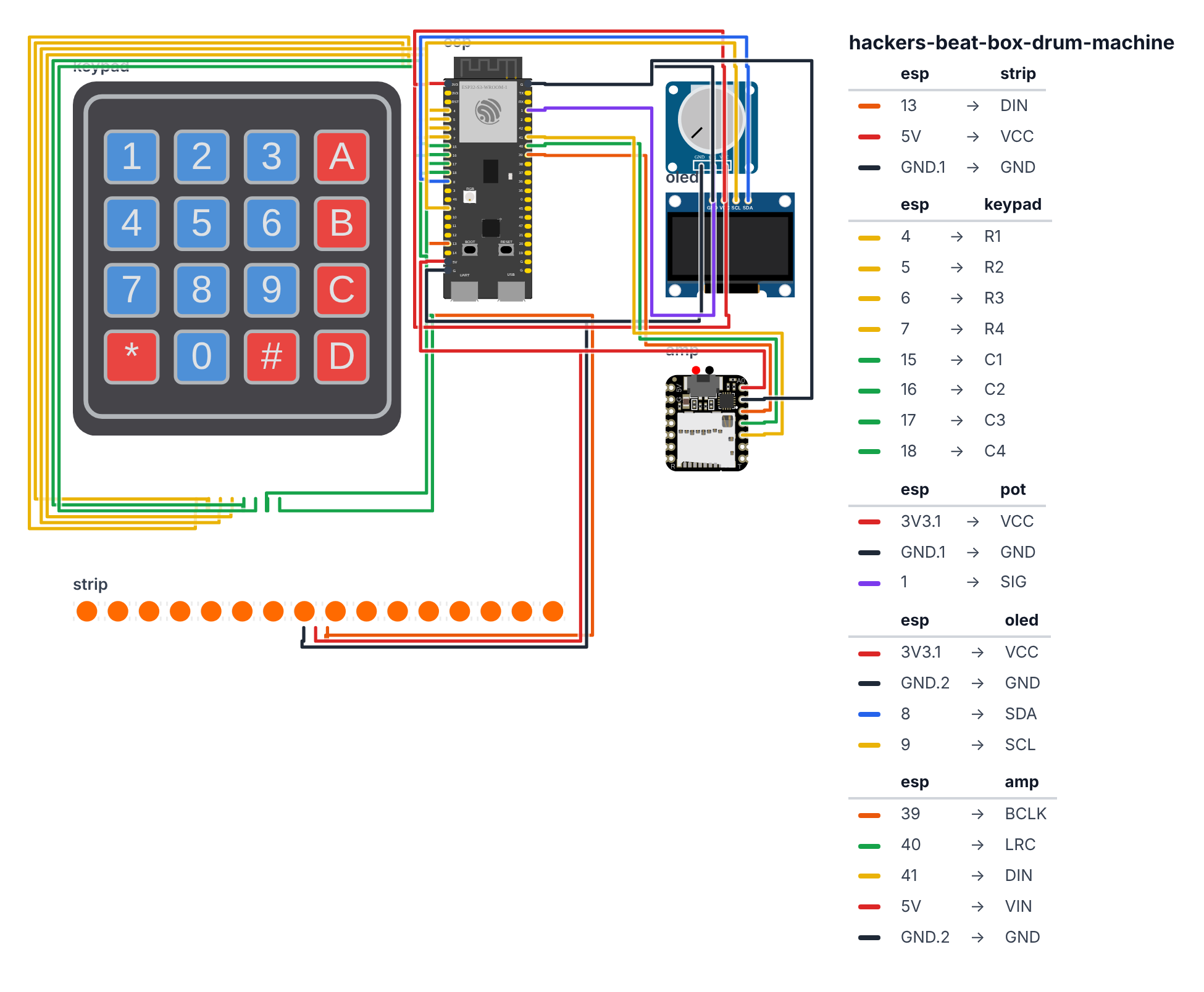
MAX98357A I2S Amplifier (3 wires):
- MAX98357A BCLK → GPIO 39 (C6: GPIO 10)
- MAX98357A LRC → GPIO 40 (C6: GPIO 11)
- MAX98357A DIN → GPIO 41 (C6: GPIO 23)
- MAX98357A VIN → 5V — red wire
- MAX98357A GND → GND — black wire
- MAX98357A OUT+ → speaker +
- MAX98357A OUT- → speaker -
WS2812B LED Strip (3 wires): 8. LED DIN → GPIO 13 (C6: GPIO 5) — orange wire 9. LED VCC → 5V — red wire 10. LED GND → GND — black wire
Button Matrix (8 wires — 4 rows, 4 columns): 11. Row 0 → GPIO 4 (C6: GPIO 0) 12. Row 1 → GPIO 5 (C6: GPIO 19) 13. Row 2 → GPIO 6 (C6: GPIO 20) 14. Row 3 → GPIO 7 (C6: GPIO 21) 15. Col 0 → GPIO 15 (C6: GPIO 3) 16. Col 1 → GPIO 16 (C6: GPIO 4) 17. Col 2 → GPIO 17 (C6: GPIO 22) 18. Col 3 → GPIO 18 (C6: GPIO 18)
Tempo Potentiometer (3 wires): 19. Pot one end → 3.3V 20. Pot other end → GND 21. Pot wiper (middle) → GPIO 1 (C6: GPIO 2)
OLED (4 wires): 22. OLED SDA → GPIO 8 (C6: GPIO 6) 23. OLED SCL → GPIO 9 (C6: GPIO 7) 24. OLED VCC → 3.3V 25. OLED GND → GND
Check: Count 25 connections total. Rows go to OUTPUT pins (4–7; C6: 0, 19, 20, 21), columns go to INPUT_PULLUP pins (15–18; C6: 3, 4, 22, 18). This is the button matrix scanning trick — 16 buttons on only 8 pins.
Important: Add a 100Ω series resistor on the LED data line (between GPIO 13 (C6: GPIO 5) and the first LED’s DIN) to protect the first LED from voltage spikes.
Step 2: Upload the code
Time: ~5 minutes
Install libraries in Arduino IDE Library Manager:
- FastLED — WS2812B control
- Adafruit SSD1306 + Adafruit GFX Library — OLED
- ESP8266Audio by Earle Philhower — WAV playback (works on ESP32 too)
The big picture first. A drum machine works like a grid of on/off switches arranged in time. Time is divided into 16 equal slices (steps). For each slice, each drum is either ON or OFF. A clock sweeps through all 16 steps at your BPM speed, triggers whatever is ON, then loops back to step 1 — forever. Your 16 buttons toggle steps on and off. The LEDs show which steps are lit. The white LED sweeping across is the playhead.
// ========== CHOOSE YOUR BOARD ==========
// Uncomment the line for YOUR board:
#define BOARD_S3    // ESP32-S3-DevKitC-1
//#define BOARD_C6  // ESP32-C6-DevKitC-1
// ========================================

#ifdef BOARD_S3
  #define PIN_ROW0             4
  #define PIN_ROW1             5
  #define PIN_ROW2             6
  #define PIN_ROW3             7
  #define PIN_COL0             15
  #define PIN_COL1             16
  #define PIN_COL2             17
  #define PIN_COL3             18
  #define PIN_TEMPO            1
  #define PIN_NEOPIXEL         13
  #define PIN_I2S_BCLK         39
  #define PIN_I2S_LRC          40
  #define PIN_I2S_DOUT         41
  #define PIN_SDA              8
  #define PIN_SCL              9
#endif
#ifdef BOARD_C6
  #define PIN_ROW0             0
  #define PIN_ROW1             19
  #define PIN_ROW2             20
  #define PIN_ROW3             21
  #define PIN_COL0             3
  #define PIN_COL1             4
  #define PIN_COL2             22
  #define PIN_COL3             18
  #define PIN_TEMPO            2
  #define PIN_NEOPIXEL         5
  #define PIN_I2S_BCLK         10
  #define PIN_I2S_LRC          11
  #define PIN_I2S_DOUT         23
  #define PIN_SDA              6
  #define PIN_SCL              7
#endif

#include <Wire.h>
#include <Adafruit_SSD1306.h>
#include <FastLED.h>
#include "AudioFileSourceSPIFFS.h"
#include "AudioGeneratorWAV.h"
#include "AudioOutputI2S.h"

const int ROW_PINS[4] = {PIN_ROW0, PIN_ROW1, PIN_ROW2, PIN_ROW3};
const int COL_PINS[4] = {PIN_COL0, PIN_COL1, PIN_COL2, PIN_COL3};
const int TEMPO_PIN   = PIN_TEMPO;
const int LED_PIN     = PIN_NEOPIXEL;
const int I2S_BCLK    = PIN_I2S_BCLK;
const int I2S_LRC     = PIN_I2S_LRC;
const int I2S_DOUT    = PIN_I2S_DOUT;

#define NUM_LEDS 16
CRGB leds[NUM_LEDS];

const char* SAMPLES[4] = {"/kick.wav", "/snare.wav", "/hihat.wav", "/clap.wav"};
const CRGB  DRUM_COLORS[4] = {CRGB::Red, CRGB::Blue, CRGB::Yellow, CRGB::Green};
const char* DRUM_NAMES[4]  = {"KICK", "SNARE", "HAT", "CLAP"};

bool pattern[4][16] = {{false}};
int  currentTrack   = 0;
int  currentStep    = 0;
bool isPlaying      = true;
int  bpm            = 120;
unsigned long lastStep = 0;

AudioFileSourceSPIFFS* source   = nullptr;
AudioGeneratorWAV*     wav      = nullptr;
AudioOutputI2S*        i2sOut   = nullptr;

Adafruit_SSD1306 display(128, 64, &Wire, -1);

void playDrum(int track) {
  if (wav && wav->isRunning()) {
    wav->stop();
    source->close();
  }
  if (!i2sOut) {
    i2sOut = new AudioOutputI2S();
    i2sOut->SetPinout(I2S_BCLK, I2S_LRC, I2S_DOUT);
    i2sOut->SetGain(0.8);
  }
  source = new AudioFileSourceSPIFFS(SAMPLES[track]);
  wav    = new AudioGeneratorWAV();
  wav->begin(source, i2sOut);
}

int scanMatrix() {
  for (int r = 0; r < 4; r++) {
    for (int i = 0; i < 4; i++) digitalWrite(ROW_PINS[i], HIGH);
    digitalWrite(ROW_PINS[r], LOW);
    delayMicroseconds(10);
    for (int c = 0; c < 4; c++) {
      if (digitalRead(COL_PINS[c]) == LOW) {
        for (int i = 0; i < 4; i++) digitalWrite(ROW_PINS[i], HIGH);
        return r * 4 + c;
      }
    }
  }
  for (int i = 0; i < 4; i++) digitalWrite(ROW_PINS[i], HIGH);
  return -1;
}

void updateLEDs() {
  for (int i = 0; i < 16; i++) {
    if (i == currentStep && isPlaying) {
      leds[i] = CRGB::White;
    } else if (pattern[currentTrack][i]) {
      leds[i] = DRUM_COLORS[currentTrack];
    } else {
      leds[i] = CRGB(8, 8, 8);
    }
  }
  FastLED.show();
}

void setup() {
  for (int i = 0; i < 4; i++) {
    pinMode(ROW_PINS[i], OUTPUT);
    digitalWrite(ROW_PINS[i], HIGH);
    pinMode(COL_PINS[i], INPUT_PULLUP);
  }

  FastLED.addLeds<WS2812B, LED_PIN, GRB>(leds, NUM_LEDS);
  FastLED.setBrightness(60);

  Wire.begin(PIN_SDA, PIN_SCL);
  display.begin(SSD1306_SWITCHCAPVCC, 0x3C);
  display.setTextColor(WHITE);

  SPIFFS.begin(true);
}

void loop() {
  int potVal = analogRead(TEMPO_PIN);
  bpm = map(potVal, 0, 4095, 60, 200);

  unsigned long stepMs = 60000UL / (bpm * 4);
  if (isPlaying && (millis() - lastStep >= stepMs)) {
    lastStep = millis();
    for (int t = 0; t < 4; t++) {
      if (pattern[t][currentStep]) {
        playDrum(t);
        break;
      }
    }
    currentStep = (currentStep + 1) % 16;
  }

  if (wav && wav->isRunning()) {
    wav->loop();
  }

  static int lastPressed = -1;
  static unsigned long lastPressTime = 0;
  int pressed = scanMatrix();
  if (pressed != lastPressed && pressed != -1) {
    if (millis() - lastPressTime > 50) {
      pattern[currentTrack][pressed] = !pattern[currentTrack][pressed];
      lastPressTime = millis();
    }
  }
  lastPressed = pressed;

  updateLEDs();

  static unsigned long lastDisplay = 0;
  if (millis() - lastDisplay > 50) {
    lastDisplay = millis();
    display.clearDisplay();
    display.setTextSize(1);
    display.setCursor(0, 0);
    display.print(DRUM_NAMES[currentTrack]);
    display.print("  BPM:");
    display.print(bpm);
    display.setCursor(0, 10);
    display.print("STEP:");
    display.print(currentStep + 1);
    display.print("/16");

    for (int i = 0; i < 16; i++) {
      int px = (i % 8) * 8;
      int py = 30 + (i / 8) * 10;
      if (pattern[currentTrack][i]) {
        display.fillRect(px, py, 6, 8, WHITE);
      } else {
        display.drawRect(px, py, 6, 8, WHITE);
      }
    }
    display.display();
  }
}
Line-by-line: what every line does and why
Lines 1–6: Instruction books
Three audio books: Adafruit_SSD1306 for the screen, FastLED for the LEDs, and three audio books (AudioFileSourceSPIFFS, AudioGeneratorWAV, AudioOutputI2S) that work together like a chain — read file from flash → decode WAV → send to speaker.
Lines 8–16: Pin assignments
const int ROW_PINS[4] = {PIN_ROW0, PIN_ROW1, PIN_ROW2, PIN_ROW3};
const int COL_PINS[4] = {PIN_COL0, PIN_COL1, PIN_COL2, PIN_COL3};
const int means “a number that never changes.” Instead of 16 individual button pins, you use a 4×4 matrix: 4 row output pins + 4 column input pins = 8 pins for 16 buttons. This is how every keyboard in the world works.
Lines 22–26: Drum track data
const char* SAMPLES[4] = {"/kick.wav", "/snare.wav", "/hihat.wav", "/clap.wav"};
const CRGB  DRUM_COLORS[4] = {CRGB::Red, CRGB::Blue, CRGB::Yellow, CRGB::Green};
These are arrays — lists with four slots each. Slot 0 = kick, slot 1 = snare, etc. When currentTrack = 0, the LEDs show red and the audio plays kick.wav. Using arrays like this means you can change all four tracks by editing one list.
Lines 28–34: Sequencer state
bool pattern[4][16] = {{false}};
int  currentStep    = 0;
int  bpm            = 120;
pattern[4][16] is a grid — 4 rows (drum tracks) × 16 columns (time steps). Each cell is true (beat on) or false (beat off). currentStep is the playhead position — which column is playing right now. bpm = 120 means 120 beats per minute — standard dance tempo.
scanMatrix(): Reading 16 buttons with 8 pins
for (int r = 0; r < 4; r++) {
  for (int i = 0; i < 4; i++) digitalWrite(ROW_PINS[i], HIGH);
  digitalWrite(ROW_PINS[r], LOW);
  delayMicroseconds(10);
  for (int c = 0; c < 4; c++) {
    if (digitalRead(COL_PINS[c]) == LOW) {
      return r * 4 + c;
    }
  }
}
return -1;
The matrix trick: set all rows HIGH, then lower one row at a time. If a button in that row is pressed, its column pin reads LOW (because the pressed button connects the LOW row to the column). r * 4 + c converts (row, column) to a number 0–15. Returns -1 if no button is pressed.
loop() — BPM from potentiometer
int potVal = analogRead(TEMPO_PIN);
bpm = map(potVal, 0, 4095, 60, 200);
analogRead returns 0–4095 (the ESP32 has a 12-bit ADC — 4096 possible values). map() converts that range to 60–200 BPM. Turn the pot clockwise: BPM goes up. Counter-clockwise: it slows down.
loop() — Sequencer clock
unsigned long stepMs = 60000UL / (bpm * 4);
if (isPlaying && (millis() - lastStep >= stepMs)) {
  currentStep = (currentStep + 1) % 16;
}
60000 / (bpm × 4) calculates how many milliseconds between steps. At 120 BPM: 60000 / 480 = 125ms per step. millis() is the stopwatch — when enough time has passed, advance to the next step. % 16 wraps around after step 15 back to step 0 — the loop repeats forever.
loop() — Button toggle
pattern[currentTrack][pressed] = !pattern[currentTrack][pressed];! means NOT. If the cell was false (beat off), it becomes true (beat on). If it was true, it becomes false. One line — a perfect toggle. The 50ms debounce check before it prevents a single button press from toggling multiple times.
The whole thing in one sentence
The loop reads the tempo pot, checks if enough time has passed to advance the step, plays whichever drums are ON at this step, reads button presses to toggle the pattern, and updates LEDs and the OLED screen 20 times per second.
First thing to try: Upload with all 4 WAV files on SPIFFS. The white LED should sweep across immediately. Press button 1 (step 1) — a kick drum should play when the white light reaches it.
Step 3: Config — switch between drum tracks
Time: ~2 minutes
Right now currentTrack is always 0 (kick). To program all 4 drums, you need to switch tracks.
Quick fix: Add a dedicated “track select” button. Wire a button between any free GPIO (say GPIO 0; C6: GPIO 9) and GND. In the loop, detect a button press and cycle currentTrack through 0, 1, 2, 3. The LED color shows which track you’re editing — red for kick, blue for snare, yellow for hi-hat, green for clap.
The OLED already shows the track name, so you always know which drum you’re programming.
Step 4: Program your first beat!
Time: ~2 minutes
The sequencer starts running immediately at 120 BPM (white LED sweeping). The 4×4 grid maps to 16 steps left-to-right, top-to-bottom.
Classic hip-hop beat: Kick on steps 1 and 9, snare on steps 5 and 13, hi-hat on all 16 steps. That’s the foundation of most hip-hop.
Basic rock beat: Kick on steps 1 and 9, snare on steps 5 and 13, hi-hat on every other step (1, 3, 5, 7…).
Techno: Kick on every 4th step (1, 5, 9, 13). Just that. Nothing else. Feel the difference?
Turn the potentiometer to change the tempo. Watch the LEDs react — the playhead sweeps faster.
What just happened (what you learned)
-
I2S (Inter-IC Sound) — a digital audio protocol: three wires (BCLK, LRC, DATA) that carry audio as a stream of numbers. The MAX98357A receives these numbers and drives a speaker directly. All digital, no analog noise.
-
Button Matrix — how keyboards and drum pads squeeze many buttons onto few pins. 16 buttons normally need 16 GPIO pins. The matrix uses 8: 4 row outputs + 4 column inputs. You drive one row LOW at a time and read which column is also LOW. The button at that intersection is pressed. This is how every keyboard in the world works.
-
SPIFFS (Serial Peripheral Interface Flash File System) — the ESP32’s onboard storage, a 4MB flash chip that acts like a tiny hard drive. You upload files once and they survive forever, including reboots. That’s why this machine sounds like real drums instead of synthesized bleeps.
-
Sequencer timing — the sequencer fires a new step every
60000 / (BPM × 4)milliseconds. At 120 BPM: 60000 / 480 = 125ms per step. Sixteen steps × 125ms = 2 seconds = one bar. The human brain starts feeling “groove” around 80–160 BPM.
Level Up
Add swing. Real drum machines don’t play on a perfectly even grid — that sounds robotic. Swing delays every odd step slightly. Add a swingAmount variable (0–30ms) and add it to odd-numbered steps: if (currentStep % 2 == 1) delay(swingAmount);. Does it feel different? That shuffle is the soul of jazz and hip-hop.
Add track switching button. Wire a button to cycle currentTrack through 0, 1, 2, 3 and program all four drum voices independently.
Upgrade to NeoTrellis. The Adafruit NeoTrellis is a 4×4 grid of NeoPixel-backlit silicone buttons that communicates over I2C — purpose-built for exactly this application. It replaces the button matrix + LED strip combination with one clean board.
★★ You completed: Beat Box Drum Machine!
Troubleshooting
| Problem | Fix |
|---|---|
| No sound from speaker | Check MAX98357A wiring: BCLK→39, LRC→40, DIN→41 (C6: BCLK→10, LRC→11, DIN→23). Check speaker polarity (OUT+ / OUT-). Check 5V power to VIN. |
| WAV files not found | Did SPIFFS upload succeed? Check that files are named exactly kick.wav etc. (lowercase). Check SPIFFS.begin() in setup(). |
| LEDs all stay off | Check DIN wire on GPIO 13 (C6: GPIO 5) with 100Ω resistor. Check 5V power to LED VCC. |
| Button doesn’t toggle step | Check matrix scan: rows on OUTPUT pins (4–7; C6: 0, 19, 20, 21), columns on INPUT_PULLUP pins (15–18; C6: 3, 4, 22, 18). |
| Tempo doesn’t change | Check pot wiper on GPIO 1 (C6: GPIO 2) (ADC). Check 3.3V/GND on pot ends (not 5V — ADC max is 3.3V). |
| OLED shows nothing | Check SDA/SCL on GPIO 8/9 (C6: GPIO 6/7). I2C address 0x3C or try 0x3D. Check 3.3V power. |