Parent info
Parts you need
Affiliate links — we may earn a small commission
Try this circuit in your browser!
Run the code, press the buttons and watch what happens — before you buy any parts. No account needed.
Open in Simulator →Your Christmas music controls the lights.
Imagine this: you press play on your Christmas playlist. Jingle Bells starts. The kick drum hits — the LEDs pulse red. The bells come in — green flashes across the strip. The high-hat shimmer turns blue.
The lights are listening. In real time. No lag, no sync cable, just a tiny microphone picking up the room.
That’s what we’re building. In about 2 hours. For around $28.
What you’ll need
| Part | What it does | Price |
|---|---|---|
| ESP32-S3 Dev Board | Runs the audio analysis and controls LEDs | ~$12 |
| WS2812B LED Strip, 1–2m | The lights — position along a mantle or windowsill | ~$6 |
| INMP441 MEMS Microphone | Picks up room audio digitally — no noise, no analog fuzz | ~$3 |
| 5V 2A Power Supply | Powers the LEDs separately from the ESP32 | ~$6 |
| 330-ohm resistor | Protects the first LED in the chain | ~$1 |
| Jumper wires (6 needed) | Connects everything | ~$2 |
You also need: a computer with Arduino IDE, some Christmas music to test with.
Total: ~$28 | Time: ~2 hours | Difficulty: ●●○○○
Tip: Position the strip along your mantle or windowsill. Put the microphone on a shelf where it can hear the room without being pressed against a speaker — 1–2 metres from your audio source is ideal.
How it works (60 seconds)
Think of it like a prism splitting white light into a rainbow — except instead of light, it splits sound into bass, mids, and highs.
The INMP441 microphone records the room digitally — not as a fuzzy analog signal, but as precise numbers 44,100 times per second. The ESP32 takes 256 of those numbers, runs a Fast Fourier Transform (FFT) on them, and separates them into frequency buckets. Low numbers = bass. Medium numbers = melody. High numbers = cymbal shimmer.
Each bucket gets mapped to a brightness level on a section of the LED strip:
- Bass (kick drum, bass guitar) → red zone
- Mids (vocals, melody) → green zone
- Highs (hi-hats, bells) → blue zone
The whole thing runs 30+ times per second. That’s why it looks reactive and real, not laggy and fake.
Step 0: Install the extra library
Time: ~2 minutes
You need one library that doesn’t come pre-installed:
- Open Arduino IDE.
- Go to Sketch → Include Library → Manage Libraries.
- Search for “arduinoFFT” and click Install.
- Also install “FastLED” if you haven’t already.
Check: Both libraries show a green checkmark (or “INSTALLED”) in the Library Manager. Close it when done.
Step 1: Wire the microphone
Time: ~10 minutes
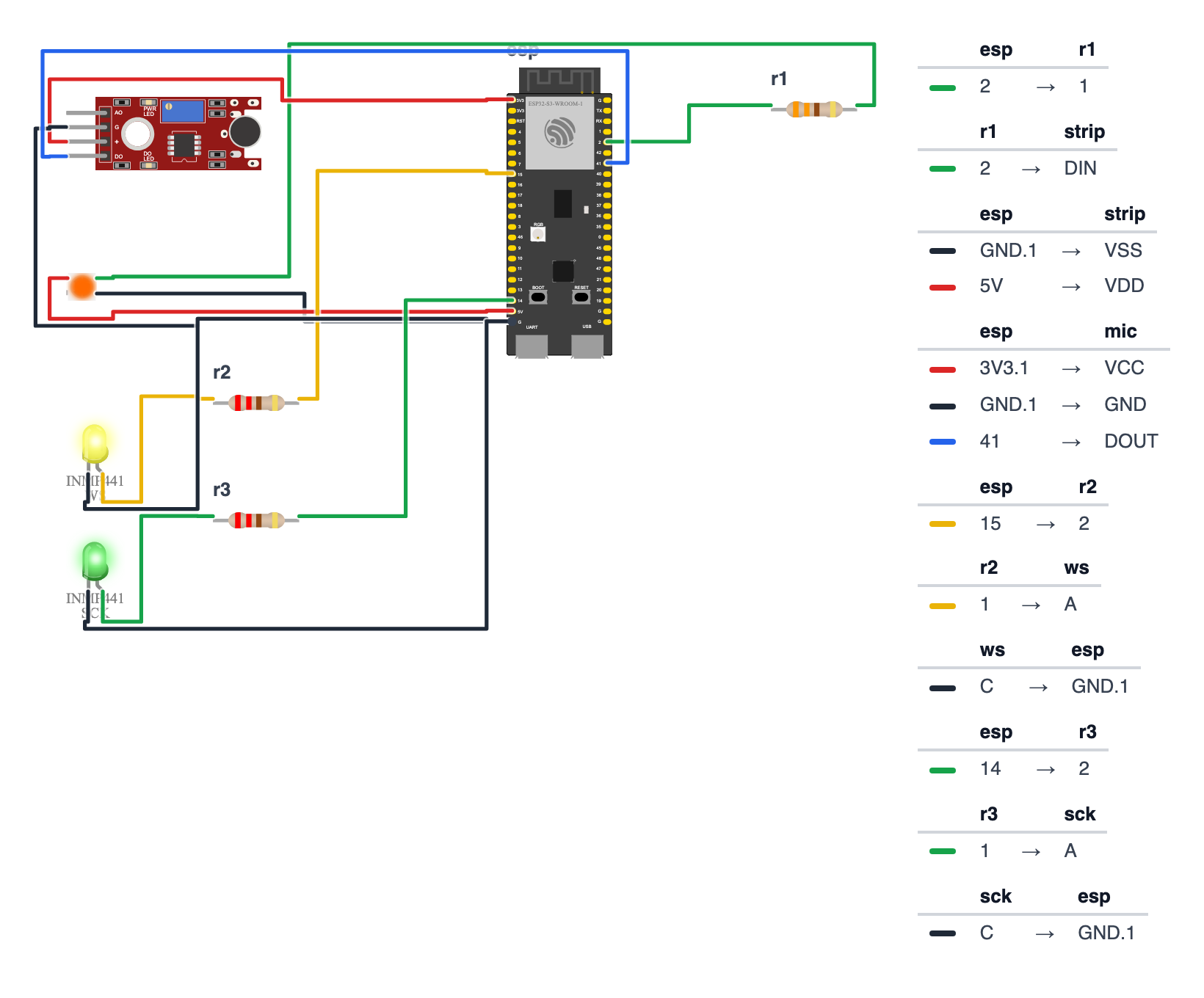
The INMP441 connects via I2S — a digital audio protocol. It has 6 pins. You’ll connect all of them.
INMP441 → ESP32:
- INMP441 VDD → ESP32 3.3V — red wire
- INMP441 GND → ESP32 GND — black wire
- INMP441 SD (data) → ESP32 GPIO 41 (C6: GPIO 5) — blue wire
- INMP441 WS (word select) → ESP32 GPIO 15 (C6: GPIO 3) — yellow wire
- INMP441 SCK (clock) → ESP32 GPIO 14 (C6: GPIO 4) — green wire
- INMP441 L/R pin → ESP32 GND — black wire (this selects left channel)
Check: The L/R pin MUST be connected to GND. If it’s floating (unconnected), the microphone outputs nothing. This is the most common wiring mistake on this project.
Step 2: Wire the LED strip
Time: ~5 minutes
Same as Project 1. The LED strip power comes from the 5V supply, not the ESP32.
LED strip power:
- Strip VCC → 5V supply +5V — red wire
- Strip GND → 5V supply GND + ESP32 GND — black wire
LED strip data: 3. Strip DIN → one leg of 330-ohm resistor → ESP32 GPIO 2 (C6: GPIO 8) — any colour
Check: You should have 9 wires total: 6 for the mic, 3 for the strip. The ESP32’s GND pin connects to both the mic’s GND and the power supply’s GND. That shared GND is what makes the whole circuit work.
Step 3: Upload the code
Time: ~10 minutes
The big picture first. This program turns the ESP32 into a music visualiser — it listens to the room with a tiny microphone and makes LEDs dance to the music in real time. The ESP32 is the brain. The INMP441 microphone listens to sound and converts it into numbers, 44,100 times per second. The ESP32 then does a mathematical trick called an FFT — think of it like a prism splitting white light into a rainbow, but for sound instead. Bass frequencies light up red LEDs. Mid frequencies light up green. High frequencies light up blue. All in real time.
A program is like a recipe. Copy this complete sketch into Arduino IDE. It reads audio, runs the FFT, and drives the LEDs.
// ========== CHOOSE YOUR BOARD ==========
// Uncomment the line for YOUR board:
#define BOARD_S3    // ESP32-S3-DevKitC-1
//#define BOARD_C6  // ESP32-C6-DevKitC-1
// ========================================

#ifdef BOARD_S3
  #define PIN_NEOPIXEL         2
  #define PIN_I2S_WS           15
  #define PIN_I2S_SCK          14
  #define PIN_I2S_SD           41
#endif
#ifdef BOARD_C6
  #define PIN_NEOPIXEL         8
  #define PIN_I2S_WS           3
  #define PIN_I2S_SCK          4
  #define PIN_I2S_SD           5
#endif

#include <FastLED.h>
#include <driver/i2s.h>
#include <arduinoFFT.h>

#define LED_PIN      PIN_NEOPIXEL
#define NUM_LEDS     60
#define BRIGHTNESS   120
CRGB leds[NUM_LEDS];

#define I2S_WS       PIN_I2S_WS
#define I2S_SCK      PIN_I2S_SCK
#define I2S_SD       PIN_I2S_SD
#define I2S_PORT     I2S_NUM_0
#define SAMPLE_RATE  44100
#define SAMPLES      256

double vReal[SAMPLES];
double vImag[SAMPLES];
ArduinoFFT<double> FFT = ArduinoFFT<double>(vReal, vImag, SAMPLES, SAMPLE_RATE);

float bassLevel  = 0;
float midLevel   = 0;
float highLevel  = 0;
const float SMOOTH = 0.3f;
const float SENSITIVITY = 0.00000008f;

void setupI2S() {
  i2s_config_t i2s_config = {
    .mode = (i2s_mode_t)(I2S_MODE_MASTER | I2S_MODE_RX),
    .sample_rate = SAMPLE_RATE,
    .bits_per_sample = I2S_BITS_PER_SAMPLE_32BIT,
    .channel_format = I2S_CHANNEL_FMT_ONLY_LEFT,
    .communication_format = I2S_COMM_FORMAT_STAND_I2S,
    .intr_alloc_flags = ESP_INTR_FLAG_LEVEL1,
    .dma_buf_count = 8,
    .dma_buf_len = SAMPLES,
    .use_apll = false,
    .tx_desc_auto_clear = false,
    .fixed_mclk = 0
  };
  i2s_pin_config_t pin_config = {
    .bck_io_num   = I2S_SCK,
    .ws_io_num    = I2S_WS,
    .data_out_num = I2S_PIN_NO_CHANGE,
    .data_in_num  = I2S_SD
  };
  i2s_driver_install(I2S_PORT, &i2s_config, 0, NULL);
  i2s_set_pin(I2S_PORT, &pin_config);
}

void readAudio() {
  int32_t samples[SAMPLES];
  size_t bytesRead = 0;
  i2s_read(I2S_PORT, samples, sizeof(samples), &bytesRead, portMAX_DELAY);
  int count = bytesRead / sizeof(int32_t);
  for (int i = 0; i < SAMPLES; i++) {
    vReal[i] = (i < count) ? (double)(samples[i] >> 8) : 0.0;
    vImag[i] = 0.0;
  }
}

float getBandEnergy(int lowBin, int highBin) {
  float sum = 0;
  for (int i = lowBin; i <= highBin; i++) {
    sum += (float)(vReal[i] * vReal[i]);
  }
  return sum * SENSITIVITY;
}

void setup() {
  Serial.begin(115200);
  FastLED.addLeds<WS2812B, LED_PIN, GRB>(leds, NUM_LEDS);
  FastLED.setBrightness(BRIGHTNESS);
  FastLED.clear();
  FastLED.show();
  setupI2S();
  Serial.println("Musical Light Show ready! Play some music.");
}

void loop() {
  readAudio();

  FFT.windowing(FFT_WIN_TYP_HAMMING, FFT_FORWARD);
  FFT.compute(FFT_FORWARD);
  FFT.complexToMagnitude();

  float newBass  = getBandEnergy(1, 2);
  float newMid   = getBandEnergy(3, 17);
  float newHigh  = getBandEnergy(18, 60);

  bassLevel  = bassLevel  * (1 - SMOOTH) + newBass  * SMOOTH;
  midLevel   = midLevel   * (1 - SMOOTH) + newMid   * SMOOTH;
  highLevel  = highLevel  * (1 - SMOOTH) + newHigh  * SMOOTH;

  uint8_t bassB  = (uint8_t)constrain(bassLevel  * 255.0f, 0, 255);
  uint8_t midG   = (uint8_t)constrain(midLevel   * 255.0f, 0, 255);
  uint8_t highB  = (uint8_t)constrain(highLevel  * 255.0f, 0, 255);

  int third = NUM_LEDS / 3;
  for (int i = 0; i < third; i++) {
    leds[i]              = CRGB(bassB, 0, 0);
    leds[i + third]      = CRGB(0, midG, 0);
    leds[i + third * 2]  = CRGB(0, 0, highB);
  }

  fadeToBlackBy(leds, NUM_LEDS, 10);

  FastLED.show();
}
Line-by-line: what every line does and why
Lines 1–3: Borrowing three instruction books
#include <FastLED.h>
#include <driver/i2s.h>
#include <arduinoFFT.h>
#include means “grab this instruction book.”
- FastLED — how to control the LED strip.
- driver/i2s — how to receive digital audio through the I2S protocol (a standard way chips talk audio).
- arduinoFFT — the math library for splitting sound into bass, mid, and high.
Lines 5–8: LED settings
#define LED_PIN      PIN_NEOPIXEL
#define NUM_LEDS     60
#define BRIGHTNESS   120
CRGB leds[NUM_LEDS];
#define gives numbers names — like sticky notes. 60 LEDs on pin 2 (C6: pin 8) — the number comes from PIN_NEOPIXEL in the board block at the top. Brightness 120 out of 255 — roughly half. CRGB leds[60] is a shelf with 60 boxes, each holding one LED colour.
Lines 10–15: Microphone pin definitions
#define I2S_WS       PIN_I2S_WS
#define I2S_SCK      PIN_I2S_SCK
#define I2S_SD       PIN_I2S_SD
#define I2S_PORT     I2S_NUM_0
#define SAMPLE_RATE  44100
#define SAMPLES      256
I2S uses three wires: WS (Word Select — left/right clock) on pin 15, SCK (bit clock — the beat keeper) on pin 14, and SD (actual sound data) on pin 41 (C6: pins 3, 4 and 5). 44100 means the microphone sends 44,100 sound measurements every second — the same quality as a CD. SAMPLES 256 means we analyse 256 measurements at a time.
Lines 17–22: The FFT engine
double vReal[SAMPLES];
double vImag[SAMPLES];
ArduinoFFT<double> FFT = ArduinoFFT<double>(vReal, vImag, SAMPLES, SAMPLE_RATE);
FFT needs two arrays: vReal holds the actual sound measurements (256 of them). vImag holds imaginary numbers — a mathematical trick the FFT needs, all starting at zero. Think of them as two shelves: the “real” shelf holds your actual sound data, the “imaginary” shelf is the FFT’s workspace. double means a number with many decimal places (more precise than float).
ArduinoFFT<double> FFT = ... creates the FFT engine and gives it those two shelves to work with.
Lines 24–28: Level tracking and tuning
float bassLevel  = 0;
float midLevel   = 0;
float highLevel  = 0;
const float SMOOTH = 0.3f;
const float SENSITIVITY = 0.00000008f;
float bassLevel— a box holding the current bass energy.floatmeans a number with a decimal point.SMOOTH = 0.3f— the “smoothing factor.” Instead of jumping instantly to a new value, we blend 30% new + 70% old. This makes the lights fade smoothly instead of flickering.SENSITIVITY— a very small multiplier. The raw FFT output is enormous. Multiplying by this tiny number brings it into a 0–1 range we can use. If LEDs don’t react, make this bigger; if they stay maxed out, make it smaller.
setupI2S(): configuring the microphone
void setupI2S() {
  i2s_config_t i2s_config = {
    .mode = (i2s_mode_t)(I2S_MODE_MASTER | I2S_MODE_RX),
    .sample_rate = SAMPLE_RATE,
    .bits_per_sample = I2S_BITS_PER_SAMPLE_32BIT,
    ...
  };
  i2s_pin_config_t pin_config = {
    .bck_io_num   = I2S_SCK,
    .ws_io_num    = I2S_WS,
    .data_out_num = I2S_PIN_NO_CHANGE,
    .data_in_num  = I2S_SD
  };
  i2s_driver_install(I2S_PORT, &i2s_config, 0, NULL);
  i2s_set_pin(I2S_PORT, &pin_config);
}
This function sets up the microphone connection. i2s_config_t is a form you fill in with settings — mode (Master = I’m in charge, RX = receiving sound), sample rate, and bit depth. i2s_pin_config_t is another form saying which pins the three wires connect to. i2s_driver_install and i2s_set_pin apply those forms — like submitting the paperwork.
readAudio(): grabbing 256 sound samples
void readAudio() {
  int32_t samples[SAMPLES];
  size_t bytesRead = 0;
  i2s_read(I2S_PORT, samples, sizeof(samples), &bytesRead, portMAX_DELAY);
  int count = bytesRead / sizeof(int32_t);
  for (int i = 0; i < SAMPLES; i++) {
    vReal[i] = (i < count) ? (double)(samples[i] >> 8) : 0.0;
    vImag[i] = 0.0;
  }
}
int32_t samples[256]— a shelf of 256 numbers, each 32 bits (large enough for audio precision).int32_tis a whole number that can be positive or negative.i2s_read(...)— ask the microphone for 256 samples. It fills the shelf.bytesRead / sizeof(int32_t)— convert bytes to sample count (each sample takes 4 bytes).for (int i = 0; i < SAMPLES; i++)— loop through all 256 positions.samples[i] >> 8— shift the bits 8 places right. This shrinks the 32-bit audio value into a smaller range the FFT handles well. Think of it as reducing a huge number by dividing.vImag[i] = 0.0— reset the imaginary shelf to zero for each new batch.
getBandEnergy(): measuring one frequency zone
float getBandEnergy(int lowBin, int highBin) {
  float sum = 0;
  for (int i = lowBin; i <= highBin; i++) {
    sum += (float)(vReal[i] * vReal[i]);
  }
  return sum * SENSITIVITY;
}
After the FFT runs, vReal no longer holds raw sound — it holds frequency strengths. Each position (called a bin) represents a range of frequencies. Bass lives in bins 1–2, mids in bins 3–17, highs in 18–60.
sum += vReal[i] * vReal[i]— add up the square of each bin’s strength. Squaring makes big differences bigger and small differences smaller — it highlights the loud parts.return sum * SENSITIVITY— multiply by the tiny sensitivity number to bring the result into a useful range (0 to about 1).
setup(): runs once on power-on
void setup() {
  Serial.begin(115200);
  FastLED.addLeds<WS2812B, LED_PIN, GRB>(leds, NUM_LEDS);
  FastLED.setBrightness(BRIGHTNESS);
  FastLED.clear();
  FastLED.show();
  setupI2S();
  Serial.println("Musical Light Show ready! Play some music.");
}Serial.begin(115200)— open the phone line to your computer.FastLED.addLeds<...>— “I have 60 WS2812B LEDs on pin 2 (C6: pin 8), in GRB colour order.”setupI2S()— configure the microphone (the big function above).Serial.println(...)— send a message to your computer confirming it’s ready.
loop(): the heartbeat — runs forever
This is where everything comes together. Seven steps every frame:
readAudio();Step 1: grab 256 fresh sound samples from the microphone into vReal.
  FFT.windowing(FFT_WIN_TYP_HAMMING, FFT_FORWARD);
  FFT.compute(FFT_FORWARD);
  FFT.complexToMagnitude();
Step 2: run the FFT. windowing applies a mathematical shape to the data to reduce edge noise (Hamming window — a common choice). compute does the actual frequency splitting. complexToMagnitude converts the FFT results to simple strengths.
  float newBass  = getBandEnergy(1, 2);
  float newMid   = getBandEnergy(3, 17);
  float newHigh  = getBandEnergy(18, 60);
Step 3: read out the energy for each frequency zone.
bassLevel = bassLevel * (1 - SMOOTH) + newBass * SMOOTH;Step 4: smooth each value. Instead of jumping straight to newBass, keep 70% of the old value and add 30% of the new. This is like stirring a cup of tea slowly — the temperature changes gradually. This prevents LEDs from flickering on every beat.
uint8_t bassB = (uint8_t)constrain(bassLevel * 255.0f, 0, 255);Step 5: convert the 0–1 float to a 0–255 brightness. constrain makes sure we never go below 0 or above 255. uint8_t is a whole number from 0 to 255 — exactly what LED brightness needs.
  int third = NUM_LEDS / 3;
  for (int i = 0; i < third; i++) {
    leds[i]              = CRGB(bassB, 0, 0);
    leds[i + third]      = CRGB(0, midG, 0);
    leds[i + third * 2]  = CRGB(0, 0, highB);
  }
Step 6: paint the strip. Divide 60 LEDs into 3 zones of 20. First zone = red (bass). Second zone = green (mid). Third zone = blue (high). The for loop fills each zone.
  fadeToBlackBy(leds, NUM_LEDS, 10);
  FastLED.show();
Step 7: fade slightly and send to strip. The small fade (10/255) makes beats feel punchy — they rise fast and tail off. FastLED.show() sends the colours out to the physical LEDs.
The whole thing in one sentence
When powered on, the display sets up the mic and LEDs (setup). Then it loops forever: grab sound, split it into bass/mid/high, smooth the values, paint the strip in three zones, and send it — 30+ times per second.
First thing to try: clap loudly near the microphone. The red (bass) zone should flash bright. Then hiss softly. The blue (high) zone should react. If nothing happens, double the SENSITIVITY value and re-upload.
Click Upload. Wait for “Done uploading.”
Check: Open the Serial Monitor (115200 baud). You should see “Musical Light Show ready! Play some music.” If you see an error, check that arduinoFFT and FastLED are both installed.
Step 4: Play music and calibrate
Time: ~5 minutes
- Plug in the LED strip’s 5V power supply.
- Play music in the room.
- Watch the LED strip — you should see three zones reacting: a red bass zone, a green mid zone, and a blue high zone.
If the LEDs barely react: Open the code and change SENSITIVITY from 0.00000008 to 0.0000002. Re-upload.
If the LEDs are maxed out and stay bright constantly: Halve the SENSITIVITY value. Re-upload.
Check: During a quiet passage, the LEDs should dim almost completely. During a loud beat drop, they should light up bright. That’s the calibration sweet spot.
What just happened (what you learned)
-
I2S (Inter-IC Sound) is a digital audio protocol — instead of an analog signal that picks up noise, the INMP441 sends a perfectly clean stream of numbers representing sound pressure, 44,100 of them every second.
-
FFT (Fast Fourier Transform) splits a snapshot of sound into its component frequencies — like how a prism splits white light into a rainbow. FFT splits a complex sound wave into bass, mids, and highs.
-
Frequency bins are the FFT output slots — at 44100Hz with 256 samples, each bin represents about 172Hz. Bins 1-2 catch deep bass. Bins 18-60 catch bright highs.
-
Exponential smoothing — blending 30% new value with 70% old value prevents jarring jumps between frames. The same technique smooths GPS location updates on your phone.
-
The SENSITIVITY constant is your volume knob for the visualiser. Too low = nothing reacts. Too high = everything maxes out. Print
Serial.println(bassLevel)in the loop to see raw values while music plays, then find the right range.
Level Up
Christmas colour palette: Change the band colours from plain RGB to festive: bass in deep Christmas red CRGB(180, 0, 0), mids in pine green CRGB(0, 120, 20), highs in ice white CRGB(200, 220, 255).
Beat flash: When bassLevel exceeds 0.85, flash the entire strip white for one frame and back. Add a bool beatFired flag to prevent re-triggering while the bass stays high.
Map bands outward from centre: Bass controls the centre LEDs, highs the outer edges — like a VU meter expanding outward. Calculate NUM_LEDS / 2 as centre, then light LEDs outward based on each band level.
Troubleshooting
| Problem | Fix |
|---|---|
| LEDs don’t react at all | Check that the INMP441 L/R pin is connected to GND. Also increase SENSITIVITY by 10x and test again. |
| LEDs stay maxed out at full brightness | Decrease SENSITIVITY by half. Keep halving until there’s dynamic range. |
| Only one zone lights up | Clap loudly near the mic. If red (bass) reacts but blue (high) doesn’t, the music has no high content — try a different song. |
| Animation looks choppy/flickery | Increase the SMOOTH constant from 0.3 to 0.5 for more smoothing. |
| Serial Monitor shows “arduinoFFT” not found | Install arduinoFFT from Library Manager. Search exactly “arduinoFFT” — not “FFT”. |
| Microphone makes no sound | Check L/R pin is grounded. Check VDD is on 3.3V (not 5V). Check all I2S pins match the code defines. |