Parent info
Parts you need
Affiliate links — we may earn a small commission
Try this circuit in your browser!
Run the code, press the buttons and watch what happens — before you buy any parts. No account needed.
Open in Simulator →You press a button. Your desk makes music.
Imagine this: eight buttons on a breadboard. You press one — a warm sine tone fills your headphones. You twist the knob — the sound changes from smooth to buzzy to bright. You tap a pattern into a 16-step sequencer and hit play. Your homemade gadget loops a beat you just invented.
That’s a synthesizer. The Teenage Engineering Pocket Operator sells for $89. You’re building the core of it for $20.
What you’ll need
| Part | What it does | Price |
|---|---|---|
| ESP32-S3 Dev Board | Brain. Runs the audio engine at 44,100 samples/sec. | ~$12 |
| 8× Tactile buttons (6×6mm) | One octave of notes — one button per note. | ~$1 |
| Rotary encoder with push | Turn to change waveform. Push to start/stop sequencer. | ~$1 |
| 0.96” OLED (SSD1306 I2C) | Shows waveform shape, frequency, and sequencer pattern live. | ~$2 |
| 3.5mm audio jack (TRS) | Headphone or line output. | ~$1 |
| 100Ω resistor | Protects the audio pin from short circuits. | cents |
| Breadboard + jumper wires | Connects everything without soldering. | ~$5 |
Total: ~$20 | Time: ~3 hours | Difficulty: ●●●○○
How it works (60 seconds)
Think of it like a digital musician trapped inside a chip.
The ESP32 turns numbers into a voltage on its audio pin — like a DAC (digital-to-analog converter). Your code writes a number to it 44,100 times every second. Those numbers follow a pattern (a waveform), and that pattern makes the speaker cone vibrate at a specific frequency. 440 vibrations per second = A4 = concert pitch.
Different patterns = different sounds. Smooth wave = flute. Square wave = old video game. Sharp ramp = bright brass. You’ll switch between five of them with a single knob turn.
Step 0: Understand the layout
Time: ~5 minutes
Before wiring anything, picture the final layout on your breadboard:
- 8 buttons in a row across the middle — these are your notes
- Rotary encoder at one end — waveform selector + sequencer toggle
- OLED at the top — your display
- Audio jack at the side — where headphones plug in
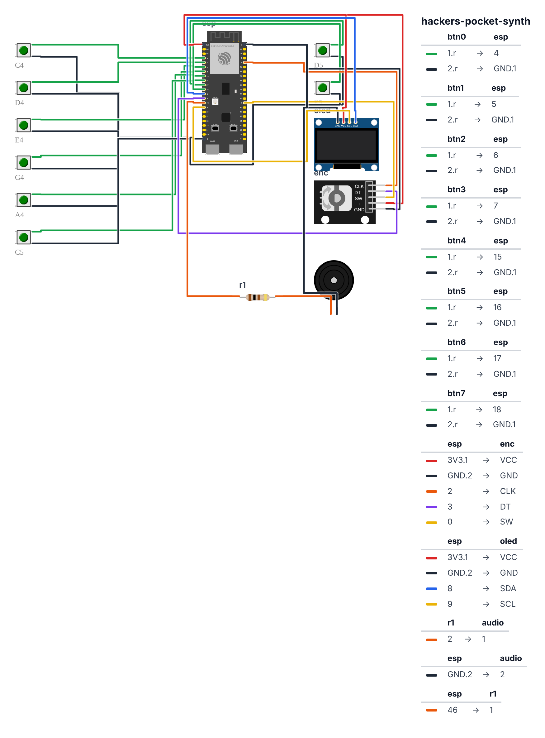
Each button connects: one leg to a GPIO pin, other leg to GND. The encoder has 5 pins: CLK, DT (rotation), SW (push), plus + and GND.
Before you start: The sound comes out of GPIO 46 (C6: GPIO 10). The ESP32-S3 and ESP32-C6 have no hardware DAC, so the code uses fast PWM instead (
ledcWrite): it switches the pin on and off 25,000 times per second, and the 100Ω resistor plus your headphones smooth that into sound.
Step 1: Wire it up
Time: ~15 minutes
Buttons (8 wires):
- Button 0 → GPIO 4 (C6: GPIO 0) | other leg → GND
- Button 1 → GPIO 5 (C6: GPIO 19) | other leg → GND
- Button 2 → GPIO 6 (C6: GPIO 20) | other leg → GND
- Button 3 → GPIO 7 (C6: GPIO 21) | other leg → GND
- Button 4 → GPIO 15 (C6: GPIO 3) | other leg → GND
- Button 5 → GPIO 16 (C6: GPIO 4) | other leg → GND
- Button 6 → GPIO 17 (C6: GPIO 22) | other leg → GND
- Button 7 → GPIO 18 (C6: GPIO 23) | other leg → GND
Rotary Encoder (5 wires): 9. Encoder CLK → GPIO 2 (C6: GPIO 11) 10. Encoder DT → GPIO 3 (C6: GPIO 1) 11. Encoder SW → GPIO 0 (C6: GPIO 15) — on the S3 this is also the BOOT pin, so don’t hold the knob down while plugging in USB 12. Encoder + → 3.3V 13. Encoder GND → GND
OLED (4 wires): 14. OLED SDA → GPIO 8 (C6: GPIO 6) 15. OLED SCL → GPIO 9 (C6: GPIO 7) 16. OLED VCC → 3.3V 17. OLED GND → GND
Audio Jack (2 wires): 18. GPIO 46 (C6: GPIO 10) → 100Ω resistor → jack TIP 19. GND → jack SLEEVE
Check: Count connections. You should have 8 button wires + 5 encoder + 4 OLED + 2 audio = 19 connections total. Board is NOT plugged in yet.
Common mistake: Wiring the encoder GND to 3.3V or vice versa. CLK and DT need to go to GPIO pins, not power rails.
Step 2: Install libraries and flash
Time: ~10 minutes
- Open Arduino IDE. Go to
File → Preferences → Additional Board Manager URLsand add:https://raw.githubusercontent.com/espressif/arduino-esp32/gh-pages/package_esp32_index.json - Install esp32 by Espressif Systems from the Board Manager.
- In Library Manager, install: Adafruit SSD1306 and Adafruit GFX Library
- Select your board:
ESP32S3 Dev Module(C6:ESP32C6 Dev Module) - Copy the complete code below into a new sketch
- Plug in USB and click Upload
Check: After upload, your OLED should show “WAVE: SINE” at the top and “—” for frequency (no button pressed = silence).
Step 3: Upload the complete code
The big picture first. A synthesizer makes sound by turning numbers into voltages many thousands of times per second — the job of a DAC (Digital-to-Analog Converter). The ESP32-S3 and C6 have no DAC chip, so the code fakes one with fast PWM on the audio pin: each number becomes a tiny average voltage. The speaker follows those voltages and vibrates at exactly the frequency you want. The ESP32 has a hardware timer that fires 44,100 times every second — like an extremely fast metronome. Each tick it runs audioISR, which calculates the next audio sample and writes it to the audio pin. The shape of those numbers over time is the waveform: a smooth hill and valley = sine wave = flute sound. Sharp on/off = square wave = old video game sound. Steadily rising then instant drop = sawtooth = bright synthesizer. The audioPhase variable is the heartbeat: it counts from 0.0 to 1.0 over exactly one wave cycle, then wraps back to 0. How fast it counts determines the frequency — count faster, the pitch rises.
// ========== CHOOSE YOUR BOARD ==========
// Uncomment the line for YOUR board:
#define BOARD_S3    // ESP32-S3-DevKitC-1
//#define BOARD_C6  // ESP32-C6-DevKitC-1
// ========================================

#ifdef BOARD_S3
  #define PIN_BTN0             4
  #define PIN_BTN1             5
  #define PIN_BTN2             6
  #define PIN_BTN3             7
  #define PIN_BTN4             15
  #define PIN_BTN5             16
  #define PIN_BTN6             17
  #define PIN_BTN7             18
  #define PIN_ENC_CLK          2
  #define PIN_ENC_DT           3
  #define PIN_ENC_SW           0
  #define PIN_AUDIO            46
  #define PIN_SDA              8
  #define PIN_SCL              9
#endif
#ifdef BOARD_C6
  #define PIN_BTN0             0
  #define PIN_BTN1             19
  #define PIN_BTN2             20
  #define PIN_BTN3             21
  #define PIN_BTN4             3
  #define PIN_BTN5             4
  #define PIN_BTN6             22
  #define PIN_BTN7             23
  #define PIN_ENC_CLK          11
  #define PIN_ENC_DT           1
  #define PIN_ENC_SW           15
  #define PIN_AUDIO            10
  #define PIN_SDA              6
  #define PIN_SCL              7
#endif

#include <Wire.h>
#include <Adafruit_SSD1306.h>
#include <math.h>

const int BTN_PINS[8] = {PIN_BTN0, PIN_BTN1, PIN_BTN2, PIN_BTN3, PIN_BTN4, PIN_BTN5, PIN_BTN6, PIN_BTN7};
const int ENC_CLK = PIN_ENC_CLK;
const int ENC_DT  = PIN_ENC_DT;
const int ENC_SW  = PIN_ENC_SW;
const int AUDIO_PIN = PIN_AUDIO;

const float NOTE_FREQ[8] = {
  261.63f, 293.66f, 329.63f, 392.00f,
  440.00f, 523.25f, 587.33f, 659.25f
};

enum Waveform { SINE, SQUARE, SAW, TRIANGLE, NOISE };
const char* WAVE_NAMES[] = {"SINE", "SQR", "SAW", "TRI", "NSE"};
volatile Waveform currentWave = SINE;

bool seqPattern[16] = {false};
int  seqStep       = 0;
bool seqPlaying    = false;
unsigned long lastStepTime = 0;
int bpm = 120;

Adafruit_SSD1306 display(128, 64, &Wire, -1);

volatile float  audioFreq  = 0.0f;
volatile float  audioPhase = 0.0f;
float           waveBuffer[64];
int             waveBufIdx = 0;

volatile int encLastCLK;
void IRAM_ATTR encoderISR() {
  int clk = digitalRead(ENC_CLK);
  int dt  = digitalRead(ENC_DT);
  if (clk != encLastCLK) {
    if (dt != clk) {
      currentWave = (Waveform)((currentWave + 1) % 5);
    } else {
      currentWave = (Waveform)((currentWave + 4) % 5);
    }
    encLastCLK = clk;
  }
}

hw_timer_t* audioTimer = NULL;
void IRAM_ATTR audioISR() {
  if (audioFreq == 0.0f) {
    ledcWrite(AUDIO_PIN, 128);
    return;
  }

  float phaseInc = audioFreq / 44100.0f;
  audioPhase += phaseInc;
  if (audioPhase >= 1.0f) audioPhase -= 1.0f;

  float sample = 0.0f;
  switch (currentWave) {
    case SINE:
      sample = sinf(audioPhase * 2.0f * M_PI);
      break;
    case SQUARE:
      sample = (audioPhase < 0.5f) ? 1.0f : -1.0f;
      break;
    case SAW:
      sample = (audioPhase * 2.0f) - 1.0f;
      break;
    case TRIANGLE:
      sample = (audioPhase < 0.5f)
        ? (audioPhase * 4.0f - 1.0f)
        : (3.0f - audioPhase * 4.0f);
      break;
    case NOISE:
      sample = ((float)esp_random() / UINT32_MAX) * 2.0f - 1.0f;
      break;
  }

  int dacVal = (int)(sample * 100.0f) + 128;
  dacVal = constrain(dacVal, 0, 255);
  ledcWrite(AUDIO_PIN, dacVal);

  waveBuffer[waveBufIdx % 64] = sample;
  waveBufIdx++;
}

void setup() {
  for (int i = 0; i < 8; i++) {
    pinMode(BTN_PINS[i], INPUT_PULLUP);
  }
  pinMode(ENC_CLK, INPUT_PULLUP);
  pinMode(ENC_DT,  INPUT_PULLUP);
  pinMode(ENC_SW,  INPUT_PULLUP);
  encLastCLK = digitalRead(ENC_CLK);
  attachInterrupt(digitalPinToInterrupt(ENC_CLK), encoderISR, CHANGE);

  ledcAttach(AUDIO_PIN, 25000, 8);

  Wire.begin(PIN_SDA, PIN_SCL);
  display.begin(SSD1306_SWITCHCAPVCC, 0x3C);
  display.clearDisplay();
  display.setTextColor(WHITE);

  audioTimer = timerBegin(44100);
  timerAttachInterrupt(audioTimer, &audioISR);
  timerAlarm(audioTimer, 1, true, 0);
}

void loop() {
  audioFreq = 0.0f;
  for (int i = 0; i < 8; i++) {
    if (digitalRead(BTN_PINS[i]) == LOW) {
      audioFreq = NOTE_FREQ[i];
      break;
    }
  }

  static bool lastEncSW = HIGH;
  bool encSW = digitalRead(ENC_SW);
  if (encSW == LOW && lastEncSW == HIGH) {
    seqPlaying = !seqPlaying;
    seqStep = 0;
  }
  lastEncSW = encSW;

  if (seqPlaying) {
    unsigned long stepInterval = 60000UL / (bpm * 4);
    if (millis() - lastStepTime >= stepInterval) {
      lastStepTime = millis();
      if (seqPattern[seqStep]) {
        audioFreq = NOTE_FREQ[seqStep % 8];
      }
      seqStep = (seqStep + 1) % 16;
    }
  }

  static unsigned long lastDisplayUpdate = 0;
  if (millis() - lastDisplayUpdate > 50) {
    lastDisplayUpdate = millis();
    display.clearDisplay();

    display.setTextSize(1);
    display.setCursor(0, 0);
    display.print("WAVE: ");
    display.print(WAVE_NAMES[currentWave]);

    display.setCursor(70, 0);
    if (audioFreq > 0) {
      display.print((int)audioFreq);
      display.print("Hz");
    } else {
      display.print("---");
    }

    for (int x = 0; x < 64; x++) {
      int idx = (waveBufIdx - 64 + x + 128) % 64;
      int y = 32 - (int)(waveBuffer[idx] * 14.0f);
      y = constrain(y, 18, 46);
      display.drawPixel(x + 32, y, WHITE);
    }

    for (int i = 0; i < 16; i++) {
      int sx = (i % 8) * 8;
      int sy = (i < 8) ? 54 : 62;
      if (seqPattern[i]) {
        display.fillRect(sx, sy, 6, 6, WHITE);
      } else {
        display.drawRect(sx, sy, 6, 6, WHITE);
      }
      if (seqPlaying && i == seqStep) {
        display.drawRect(sx - 1, sy - 1, 8, 8, WHITE);
      }
    }

    display.display();
  }

  delay(1);
}
Line-by-line: what every line does and why
Note frequencies and the pentatonic scale
const float NOTE_FREQ[8] = {
  261.63f, 293.66f, 329.63f, 392.00f,
  440.00f, 523.25f, 587.33f, 659.25f
};
These are the exact frequencies (in Hz = vibrations per second) of musical notes. 261.63 Hz is middle C on any piano. 440.00 Hz is concert A — the note every orchestra tunes to. The suffix f means “this is a floating-point number” — a number with a decimal point. The notes chosen (C, D, E, G, A) form a pentatonic scale: the five notes that sound good in any combination. Pressing multiple buttons simultaneously always sounds musical — no clashing.
enum Waveform — naming the five sound shapes
enum Waveform { SINE, SQUARE, SAW, TRIANGLE, NOISE };
volatile Waveform currentWave = SINE;
enum creates a named list. Instead of remembering that waveform 0 = sine, 1 = square, etc., you use the names directly: SINE, SQUARE. The compiler stores them as numbers internally (SINE=0, SQUARE=1, SAW=2, TRIANGLE=3, NOISE=4), but you read code that says SINE instead of 0. volatile means “this can change at any moment from the encoder interrupt — always read fresh from memory.”
The hardware timer — the audio engine’s heartbeat
  audioTimer = timerBegin(44100);
  timerAttachInterrupt(audioTimer, &audioISR);
  timerAlarm(audioTimer, 1, true, 0);
timerBegin(44100) — create a hardware timer running at 44,100 Hz (44,100 fires per second) — CD-quality audio rate. timerAttachInterrupt links the timer to the audioISR function — every tick, run audioISR. timerAlarm(audioTimer, 1, true, 0) — fire the alarm every 1 tick, auto-reload (true), on timer channel 0.
audioISR — writing one audio sample 44,100 times per second
void IRAM_ATTR audioISR() {
  if (audioFreq == 0.0f) {
    ledcWrite(AUDIO_PIN, 128);
    return;
  }
IRAM_ATTR stores this function in fast RAM so it runs in nanoseconds — it is called 44,100 times per second and cannot afford to wait for slow flash memory. If no button is pressed (audioFreq == 0), write 128 to the audio pin. The PWM range is 0–255; 128 is the midpoint — a constant neutral level with no sound. return exits the function immediately without doing anything else.
  float phaseInc = audioFreq / 44100.0f;
  audioPhase += phaseInc;
  if (audioPhase >= 1.0f) audioPhase -= 1.0f;
This is the phase accumulator — the core of all digital audio synthesis. audioPhase counts from 0.0 to 1.0, representing one complete wave cycle. phaseInc is how much to advance per sample: at 440 Hz, 440 / 44100 = 0.00997 — advance by about 1% of the cycle each sample. After 100 samples that is one complete cycle — the speaker vibrates at 440 Hz. Higher frequency = larger increment = faster counting = higher pitch.
  switch (currentWave) {
    case SINE:
      sample = sinf(audioPhase * 2.0f * M_PI);
      break;
    case SQUARE:
      sample = (audioPhase < 0.5f) ? 1.0f : -1.0f;
      break;
    case SAW:
      sample = (audioPhase * 2.0f) - 1.0f;
      break;
    case TRIANGLE:
      sample = (audioPhase < 0.5f)
        ? (audioPhase * 4.0f - 1.0f)
        : (3.0f - audioPhase * 4.0f);
      break;
    case NOISE:
      sample = ((float)esp_random() / UINT32_MAX) * 2.0f - 1.0f;
      break;
  }
switch chooses one branch based on the current waveform. case SINE: sinf() calculates the sine of the phase — a smooth hill and valley. audioPhase * 2 * π converts 0.0–1.0 into 0–360 degrees in radians. case SQUARE: if we are in the first half of the cycle (phase < 0.5), output +1. Otherwise output -1. The sharp on/off transition is what gives it that buzzy video game sound. case SAW: ramps linearly from -1 to +1, then instantly resets. case NOISE: esp_random() generates a random number from the ESP32’s hardware random number generator. Dividing by UINT32_MAX normalizes it to 0.0–1.0, then scaling to -1.0–+1.0 makes it symmetric noise, good for percussion.
  int dacVal = (int)(sample * 100.0f) + 128;
  dacVal = constrain(dacVal, 0, 255);
  ledcWrite(AUDIO_PIN, dacVal);
sample is between -1.0 and +1.0. Multiplying by 100 gives -100 to +100. Adding 128 centers it at 128 — the midpoint. The result is 28 to 228, which fits comfortably in the 0–255 range. constrain is a safety net in case any math goes slightly outside bounds. ledcWrite sends the number to the PWM output, which produces a proportional voltage after filtering.
setup — starting the sequencer and encoder
audioTimer = timerBegin(44100);Create a timer running at 44,100 Hz. In ESP32 Arduino 3.x, you just pass the desired frequency directly — the library handles the prescaler math for you. This is like telling a metronome “tick 44,100 times per second” instead of calculating gear ratios yourself.
loop — the sequencer timing
unsigned long stepInterval = 60000UL / (bpm * 4);60000 is milliseconds per minute. bpm * 4 is how many 16th notes fit in one minute (4 per beat × bpm beats per minute). At 120 BPM: 60000 / (120 × 4) = 60000 / 480 = 125 milliseconds per step. This means each of the 16 sequencer steps lasts exactly 125ms — the whole pattern repeats every 2 seconds (125ms × 16 = 2000ms). UL means “unsigned long” — tells the compiler this is a large number, not a small integer.
loop — the OLED oscilloscope
    for (int x = 0; x < 64; x++) {
      int idx = (waveBufIdx - 64 + x + 128) % 64;
      int y = 32 - (int)(waveBuffer[idx] * 14.0f);
      y = constrain(y, 18, 46);
      display.drawPixel(x + 32, y, WHITE);
    }
waveBuffer is a circular buffer of the last 64 audio samples. waveBufIdx is the write position — it keeps incrementing. The index math (waveBufIdx - 64 + x + 128) % 64 reads them in the correct order without going negative. For each of the 64 samples, y = 32 - (waveBuffer[idx] * 14) converts the -1 to +1 sample value into a vertical pixel position (center at y=32, range of ±14 pixels). A sine wave draws a smooth curve; a square wave draws two flat horizontal lines with vertical jumps between them.
The whole thing in one sentence
A hardware timer fires 44,100 times per second, and each time it reads the current note frequency, advances a phase counter by a tiny amount, calculates what value the chosen waveform should have at that phase position, and writes it to the audio pin — turning pure math into real sound through your headphones.
First thing to try: Upload, plug in headphones, press and hold button 0 — you should hear a clear tone. While holding it, turn the encoder knob to hear the same note change from smooth (sine) to buzzy (square) to bright (saw) to soft (triangle) to static (noise).
Step 4: Play it!
Time: ~2 minutes to start, infinite from there
Plug in headphones. Hold any button — you should hear a tone immediately.
Try these:
Explore waveforms: Hold button 0 (C4) and slowly turn the encoder. Listen to how the tone changes: SINE → smooth flute, SQR → buzzy video game, SAW → bright brass, TRI → soft, NSE → pure noise (great for percussion!).
Build a beat with the sequencer: While stopped, press any button — that step toggles on/off. Try pressing buttons 0, 4, 8, 12 (every 4th step). Push the encoder to start — you’ll hear a four-on-the-floor beat pattern.
Play a melody: Hold multiple buttons in sequence while the sequencer plays — the real-time notes override the sequence. You’re live-performing.
Note: This synth is monophonic — only one note at a time. The first button pressed wins. That’s how most vintage synthesizers work too.
What just happened (what you learned)
You built a working digital audio synthesizer. Here’s the science behind it:
-
Phase Accumulator — how all digital synthesizers generate audio. Instead of a lookup table, you track a 0.0–1.0 number that increments each sample. Higher frequency = bigger increment. When it reaches 1.0, wrap back to 0.0. The shape of the function applied to that number is the waveform.
-
DAC (Digital-to-Analog Converter) — turns a number (0–255) into a voltage (0–3.3V). Here fast PWM does the DAC’s job. You write numbers 44,100 times per second. The speaker turns those voltage wiggles into sound — exactly like how movies are 24 still frames per second and look like motion.
-
Hardware Timer Interrupt — runs your audio code at exactly 44,100 times per second no matter what else is happening. It’s like a reliable alarm clock that wakes up the CPU, runs the audio function, then goes back to sleep. This guarantees timing regardless of OLED drawing or button scanning.
-
Waveform character — Sine = pure tone like a tuning fork. Square = buzzy, like old NES games (rich in odd harmonics). Sawtooth = bright, classic synthesizer sound (all harmonics). Triangle = soft, halfway between sine and square. Noise = all frequencies simultaneously, useful for percussion.
-
Pentatonic scale — removes the two “problem” notes from a major scale. What’s left sounds good in any combination. That’s why mashing these buttons always sounds musical.
Level Up
Add portamento (pitch glide). Right now frequency jumps instantly. Real synths glide smoothly between notes. Track a currentFreq variable and move it toward targetFreq by a small amount each audio sample: currentFreq += (targetFreq - currentFreq) * 0.001f. The 0.001 controls glide speed.
Change the scale. Replace NOTE_FREQ[] with a blues scale (C, Eb, F, F#, G, Bb) or a chromatic scale. Different scales feel completely different emotionally. Can you feel why?
Add a reversed sawtooth. Normal sawtooth ramps from -1 to +1 then drops. Reversed: start at +1, ramp to -1. Change SAW case to: sample = 1.0f - (audioPhase * 2.0f). Does it sound different from regular saw? Why or why not?
3D-print an enclosure. Slim rectangle: 120mm × 60mm × 15mm, matte black PLA. 8 buttons in a 2×4 grid, OLED top-left, encoder top-right. No visible screws on the top face.
★★ You completed: Pocket Synth!
Troubleshooting
| Problem | Fix |
|---|---|
| No sound in headphones | Check GPIO 46 (C6: GPIO 10) → 100Ω → jack TIP. Check GND → jack SLEEVE. Try ledcWrite(AUDIO_PIN, 200) in setup to force a high PWM level — if nothing happens, the audio pin is wrong. |
| OLED stays black | Check SDA/SCL wiring (GPIO 8/9; C6: GPIO 6/7). Check OLED VCC is 3.3V (not 5V). Try I2C address 0x3D if 0x3C doesn’t work. |
| Encoder doesn’t change waveform | Check CLK on GPIO 2, DT on GPIO 3 (C6: CLK on GPIO 11, DT on GPIO 1). Try turning slowly — the interrupt fires on each detent. |
| All buttons sound the same note | Check that each button goes to its own GPIO. Multiple buttons on the same pin = same note. |
| Clicking/buzzing between notes | Normal when jumping between very different frequencies. Add portamento (see Level Up) to smooth transitions. |
| OLED shows garbage pixels | Call display.clearDisplay() before drawing and display.display() after — both are required every frame. |