Parent info
Parts you need
Affiliate links — we may earn a small commission
Try this circuit in your browser!
Run the code, press the buttons and watch what happens — before you buy any parts. No account needed.
Open in Simulator →Complete darkness. You see everything. They see nothing.
Imagine this: lights off. Total darkness. Your phone shows a live video stream of the room — every detail visible in greyscale. An 8-LED ring of infrared light you can’t see with your eyes is illuminating everything. The camera can.
This is the $25 night vision setup. The OV2640 camera on the ESP32-CAM sees near-infrared light (850nm) — completely invisible to humans. Point the IR ring at your room, start the stream, turn out the lights. The room appears dark to anyone standing in it and completely lit to you.
In 2 hours. For about $25.
What you’ll need
| Part | What it does | Price |
|---|---|---|
| ESP32-CAM (AI-Thinker) | Camera board with built-in OV2640 sensor + SD slot | ~$8 |
| IR LED Array (850nm, 8-LED ring) | Invisible light source — illuminates what only the camera can see | ~$4 |
| MicroSD card (8GB+) | Stores time-lapse photos automatically — format as FAT32 | ~$5 |
| 2N2222 NPN Transistor | Controls the IR LEDs — the GPIO can’t drive them directly | ~$1 |
| 1kΩ Resistor | Current limiting for the transistor base | ~$1 |
| 5V 1A Power Supply | Powers the camera and IR ring with enough current | ~$6 |
| FTDI USB-to-Serial Adapter | Programs the ESP32-CAM (no built-in USB) | ~$3 |
Total: ~$25 | Time: ~2 hours | Difficulty: ●●●○○
Why the transistor? The GPIO pins on the ESP32-CAM cannot source enough current to drive 8 IR LEDs directly. Each LED might need 50-100mA. The GPIO can only provide ~12mA. The 2N2222 transistor solves this: a tiny current from GPIO controls the transistor “gate,” which switches a larger current from the 5V supply to the LED array.
How it works (60 seconds)
Think of it like a TV remote — but aimed at the room instead of your TV.
TV remotes use infrared LEDs that your eyes can’t see (hold your phone camera up to a remote control and press a button — you’ll see the LED flash in the camera view but not in your eyes). Your IR ring works the same way, but with 8 LEDs in a ring pattern that floods a wider area.
The OV2640 camera chip is silicon-based, and silicon responds to wavelengths up to about 1100nm — well into the infrared range. In a completely dark room, the IR ring provides plenty of light for the sensor even though the room looks pitch black to you.
The ESP32 streams live video to your phone as MJPEG (a series of JPEG images sent continuously). Open the URL in any browser — no app needed.
Step 0: Format your SD card
Time: ~2 minutes
Format the MicroSD card as FAT32 before doing anything else.
Mac: Disk Utility → select card → Erase → “MS-DOS (FAT)” format Windows: File Explorer → right-click drive → Format → FAT32
Step 1: Wire it up
Time: ~15 minutes
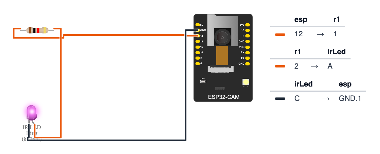
This build has two wiring phases. The transistor circuit is the new concept here.
Transistor + IR LED Ring:
The 2N2222 transistor has 3 pins. Hold it with the flat side facing you. From left to right: Emitter | Base | Collector.
ESP32-CAM GPIO 12 ── [1kΩ resistor] ─── 2N2222 Base
2N2222 Emitter ──────────────────────── GND
5V power supply ─────────────────────── IR LED Ring (+)
IR LED Ring (-) ─────────────────────── 2N2222 Collector
In breadboard terms:
- GPIO 12 → one leg of 1kΩ resistor
- Other leg of resistor → Base pin (middle pin) of 2N2222
- Emitter pin (left) → GND
- 5V power supply → IR LED ring positive terminal
- IR LED ring negative terminal → Collector pin (right) — the transistor is the switch between the ring and GND
- The GND of the 5V supply and the ESP32-CAM’s GND must be connected together
Good to know: the wiring picture leaves out the transistor (the drawing tool has no transistor part), so there the 1kΩ resistor seems to go from GPIO 12 straight to the IR ring. Build the real circuit exactly as in steps 1–6: 1kΩ to the Base, ring from 5V to the Collector, Emitter to GND.
Why GPIO 12 and not GPIO 4? On the AI-Thinker ESP32-CAM, GPIO 4 is wired to the board’s bright white flash LED — using it would switch on a very visible white light together with your “invisible” IR ring. The SD card uses GPIO 2, 14 and 15 (the code starts it in 1-bit mode,
SD_MMC.begin("/sdcard", true), so it leaves GPIO 12 and 13 free). GPIO 12 has one rule: it must be LOW when the board starts, or the board won’t boot. The resistor + transistor never pull it HIGH, so the IR ring is a perfect job for GPIO 12 — but never put a sensor that sends HIGH (like a PIR) on GPIO 12.
PIR/Programming connections (FTDI adapter for uploading code only):
| FTDI | ESP32-CAM |
|---|---|
| TX | U0R (RX) |
| RX | U0T (TX) |
| GND | GND |
| 5V | 5V |
Also connect IO0 → GND during upload, remove after.
Check: Before powering on, verify the transistor orientation. Flat side facing you: left pin = Emitter (to GND), middle = Base (to resistor), right = Collector (to the ring’s − terminal). Reversed transistor = no IR light and potentially a damaged component.
Step 2: Flash the code
Time: ~15 minutes
In Arduino IDE: select AI Thinker ESP32-CAM as the board. Hold IO0 to GND, then upload:
The big picture first. This program turns the ESP32-CAM into a night vision streaming camera:
- The IR LED ring is like a flashlight — but invisible. It floods the room with infrared light (850nm). Your eyes can’t see it, but the camera can.
- The camera streams live video to your phone over WiFi as a series of JPEG images sent one after another — called MJPEG, like a flipbook.
- Every 60 seconds, the code also saves one photo to the SD card as a time-lapse frame.
- The transistor circuit is a switch: a tiny signal from the ESP32 controls a bigger current from the 5V power supply going to the IR ring.
// Note: This project requires ESP32-S3 or ESP32-CAM (camera)

#include "esp_camera.h"
#include "esp_http_server.h"
#include "SD_MMC.h"

#define PWDN_GPIO_NUM     32
#define RESET_GPIO_NUM    -1
#define XCLK_GPIO_NUM      0
#define SIOD_GPIO_NUM     26
#define SIOC_GPIO_NUM     27
#define Y9_GPIO_NUM       35
#define Y8_GPIO_NUM       34
#define Y7_GPIO_NUM       39
#define Y6_GPIO_NUM       36
#define Y5_GPIO_NUM       21
#define Y4_GPIO_NUM       19
#define Y3_GPIO_NUM       18
#define Y2_GPIO_NUM        5
#define VSYNC_GPIO_NUM    25
#define HREF_GPIO_NUM     23
#define PCLK_GPIO_NUM     22

#define IR_LED_PIN         12
#define TIMELAPSE_INTERVAL 60000

#define WIFI_SSID     "YourWiFiName"
#define WIFI_PASSWORD "YourWiFiPassword"

#include <WiFi.h>

unsigned long lastCapture = 0;
int captureCount = 0;

bool initCamera() {
  camera_config_t config;
  config.ledc_channel = LEDC_CHANNEL_0;
  config.ledc_timer   = LEDC_TIMER_0;
  config.pin_d0  = Y2_GPIO_NUM;  config.pin_d1  = Y3_GPIO_NUM;
  config.pin_d2  = Y4_GPIO_NUM;  config.pin_d3  = Y5_GPIO_NUM;
  config.pin_d4  = Y6_GPIO_NUM;  config.pin_d5  = Y7_GPIO_NUM;
  config.pin_d6  = Y8_GPIO_NUM;  config.pin_d7  = Y9_GPIO_NUM;
  config.pin_xclk     = XCLK_GPIO_NUM;
  config.pin_pclk     = PCLK_GPIO_NUM;
  config.pin_vsync    = VSYNC_GPIO_NUM;
  config.pin_href     = HREF_GPIO_NUM;
  config.pin_sscb_sda = SIOD_GPIO_NUM;
  config.pin_sscb_scl = SIOC_GPIO_NUM;
  config.pin_pwdn     = PWDN_GPIO_NUM;
  config.pin_reset    = RESET_GPIO_NUM;
  config.xclk_freq_hz = 20000000;
  config.pixel_format = PIXFORMAT_JPEG;
  config.frame_size   = FRAMESIZE_VGA;
  config.jpeg_quality = 10;
  config.fb_count     = 2;
  return esp_camera_init(&config) == ESP_OK;
}

#define PART_BOUNDARY "123456789000000000000987654321"
static const char* STREAM_CONTENT_TYPE =
  "multipart/x-mixed-replace;boundary=" PART_BOUNDARY;
static const char* STREAM_BOUNDARY =
  "\r\n--" PART_BOUNDARY "\r\n";
static const char* STREAM_PART =
  "Content-Type: image/jpeg\r\nContent-Length: %u\r\n\r\n";

esp_err_t stream_handler(httpd_req_t* req) {
  esp_err_t res = httpd_resp_set_type(req, STREAM_CONTENT_TYPE);
  if (res != ESP_OK) return res;

  while (true) {
    camera_fb_t* fb = esp_camera_fb_get();
    if (!fb) { Serial.println("Camera capture failed"); break; }

    char part_buf[64];
    size_t hlen = snprintf(part_buf, 64, STREAM_PART, fb->len);

    httpd_resp_send_chunk(req, STREAM_BOUNDARY, strlen(STREAM_BOUNDARY));
    httpd_resp_send_chunk(req, part_buf, hlen);
    httpd_resp_send_chunk(req, (const char*)fb->buf, fb->len);

    esp_camera_fb_return(fb);
  }
  return ESP_OK;
}

void captureTimelapse() {
  camera_fb_t* fb = esp_camera_fb_get();
  if (!fb) return;

  captureCount++;
  String filename = "/tl_" + String(captureCount) + ".jpg";
  File file = SD_MMC.open(filename.c_str(), FILE_WRITE);
  if (file) {
    file.write(fb->buf, fb->len);
    file.close();
    Serial.println("Time-lapse saved: " + filename);
  }
  esp_camera_fb_return(fb);
}

void setup() {
  Serial.begin(115200);

  pinMode(IR_LED_PIN, OUTPUT);
  digitalWrite(IR_LED_PIN, HIGH);
  Serial.println("IR LEDs: ON");

  if (!initCamera()) {
    Serial.println("Camera init FAILED"); return;
  }
  Serial.println("Camera: OK");

  if (!SD_MMC.begin("/sdcard", true)) {
    Serial.println("SD card failed"); return;
  }
  Serial.println("SD card: OK");

  WiFi.begin(WIFI_SSID, WIFI_PASSWORD);
  while (WiFi.status() != WL_CONNECTED) {
    delay(500); Serial.print(".");
  }
  Serial.println("\nLive stream: http://" + WiFi.localIP().toString() + "/stream");

  httpd_config_t httpConfig = HTTPD_DEFAULT_CONFIG();
  httpd_handle_t server = NULL;
  httpd_start(&server, &httpConfig);

  httpd_uri_t streamUri = {
    .uri      = "/stream",
    .method   = HTTP_GET,
    .handler  = stream_handler,
    .user_ctx = NULL
  };
  httpd_register_uri_handler(server, &streamUri);

  Serial.println("Operation Dark Watch: ARMED");
}

void loop() {
  unsigned long now = millis();
  if (now - lastCapture > TIMELAPSE_INTERVAL) {
    lastCapture = now;
    captureTimelapse();
  }
  delay(10);
}
Line-by-line: what every line does and why
Lines 1–3: Borrowing ready-made tools
#include "esp_camera.h"
#include "esp_http_server.h"
#include "SD_MMC.h"
#include grabs instruction books.
- esp_camera — controls the OV2640 camera chip built into the ESP32-CAM board.
- esp_http_server — a lightweight web server built into the ESP-IDF framework. Faster than Arduino’s
WebServerfor streaming because it handles connections in background tasks. - SD_MMC — reads and writes the SD card.
Lines 5–24: Camera pin numbers
#define PWDN_GPIO_NUM     32
#define RESET_GPIO_NUM    -1
...
The OV2640 camera chip connects to the ESP32 through 16 wires inside the board. Each #define names the correct pin number. These numbers are specific to the AI-Thinker board layout — do not change them.
#define WIFI_SSID "YourWiFiName" — here the WiFi settings use #define instead of const char*. Both work; #define replaces the text at compile time, before the program runs.
Lines 29–30: Global timing variables
unsigned long lastCapture = 0;
int captureCount = 0;
lastCapture = 0 — a sticky note: “when did we last save a time-lapse photo?” Starts at 0, gets updated each time.
captureCount — tally counter for time-lapse filenames: tl_1.jpg, tl_2.jpg, etc.
Lines 32–50: initCamera() — camera settings
config.fb_count = 2;Most settings here are the same as the Motion Trigger project. The key difference: fb_count = 2 — two frame buffers instead of one. Why?
Think of it like a two-slot toaster vs a one-slot toaster. With two slots (two frame buffers), the camera fills one buffer while the other is being sent to your phone over WiFi. Without this, the camera would have to wait for each frame to finish sending before capturing the next one — cutting frame rate roughly in half.
Lines 52–83: The MJPEG streaming system
#define PART_BOUNDARY "123456789000000000000987654321"
static const char* STREAM_CONTENT_TYPE = "multipart/x-mixed-replace;boundary=" PART_BOUNDARY;
MJPEG (Motion JPEG) is not a real video format. It’s a trick: the browser opens one HTTP connection and expects to receive parts separated by a boundary marker. Each “part” is one JPEG image. The browser displays each new part, replacing the previous one. From your eyes, this looks like video — like a digital flipbook.
PART_BOUNDARY is the separator string between frames — a unique sequence of digits that won’t appear inside a JPEG image.
esp_err_t stream_handler(httpd_req_t* req) {
  ...
  while (true) {
    camera_fb_t* fb = esp_camera_fb_get();
    ...
    httpd_resp_send_chunk(req, STREAM_BOUNDARY, strlen(STREAM_BOUNDARY));
    httpd_resp_send_chunk(req, part_buf, hlen);
    httpd_resp_send_chunk(req, (const char*)fb->buf, fb->len);
    esp_camera_fb_return(fb);
  }
}
stream_handler is the function the web server calls when a browser opens /stream.
while (true) — an infinite loop. The function never returns. The HTTP connection stays open. Each iteration sends one frame in three chunks: the boundary separator, the content header (saying “here comes a JPEG of this many bytes”), and the actual JPEG data.
esp_camera_fb_return(fb) — critical! After sending the frame, return the buffer to the camera system so it can be refilled. Without this, the camera runs out of buffers after 2 frames (we set fb_count = 2) and stops working.
snprintf(part_buf, 64, STREAM_PART, fb->len) — snprintf formats a string, like String.format() in Python. It inserts fb->len (the JPEG file size in bytes) into the header string. The browser needs to know the size to know when one frame ends and the next begins.
Lines 85–100: captureTimelapse() — saves one photo
void captureTimelapse() {
  camera_fb_t* fb = esp_camera_fb_get();
  if (!fb) return;
  captureCount++;
  String filename = "/tl_" + String(captureCount) + ".jpg";
  File file = SD_MMC.open(filename.c_str(), FILE_WRITE);
  if (file) {
    file.write(fb->buf, fb->len);
    file.close();
  }
  esp_camera_fb_return(fb);
}
This works exactly like the Motion Trigger project’s save function. Grab a frame, build a numbered filename, open the file, write the JPEG bytes, close the file, return the buffer. Simple save to disk.
Lines 102–135: setup() — morning routine
pinMode(IR_LED_PIN, OUTPUT);
digitalWrite(IR_LED_PIN, HIGH);
Turn on IR LEDs first — before the camera captures anything. Why first? Because the camera’s first frame is taken during setup for stabilization. If the IR LEDs are off at that moment, the first stored frame is black.
digitalWrite(IR_LED_PIN, HIGH) — writing HIGH to GPIO 12 sends a small current into the 2N2222 transistor’s Base pin. The transistor then switches on a larger current from the 5V supply to the IR LED ring. GPIO can only provide ~12mA; the ring needs ~200mA. The transistor is the amplifier between them.
if (!SD_MMC.begin("/sdcard", true)) {SD_MMC.begin("/sdcard", true) mounts the SD card in 1-bit mode. In the default 4-bit mode the card would also take GPIO 4, 12 and 13 — and GPIO 12 is your IR ring. 1-bit mode is a little slower, but one photo a minute is easy.
After camera init and SD card init:
httpd_config_t httpConfig = HTTPD_DEFAULT_CONFIG();
httpd_handle_t server = NULL;
httpd_start(&server, &httpConfig);
httpd_uri_t streamUri = { .uri = "/stream", ... };
httpd_register_uri_handler(server, &streamUri);
HTTPD_DEFAULT_CONFIG() fills a settings form with sensible defaults. httpd_start() launches the web server as a background task on the ESP32’s second core. httpd_register_uri_handler tells the server: “when someone opens /stream, call stream_handler.”
Lines 137–145: loop() — time-lapse timing
void loop() {
  unsigned long now = millis();
  if (now - lastCapture > TIMELAPSE_INTERVAL) {
    lastCapture = now;
    captureTimelapse();
  }
  delay(10);
}
loop() only handles time-lapse timing. The video stream runs entirely in its own background task — loop() doesn’t need to do anything for streaming.
millis() is the stopwatch. now - lastCapture > 60000 means “has it been more than 60 seconds since the last photo?” When yes, save one time-lapse frame and reset the timer.
delay(10) — sleep 10ms between checks. The stream task continues running during this sleep.
The whole thing in one sentence
At startup, the IR LEDs turn on and the web server launches; then loop() saves one time-lapse photo every 60 seconds while the background streaming task sends live video to any browser watching /stream.
First thing to try: after uploading, open the stream URL on your phone, then turn the room lights off. The stream should stay bright and clear in greyscale from the IR ring. Hold your hand in front of the IR ring — you can feel the warmth even though you can’t see the light.
Check: Open Serial Monitor at 115200 baud. You should see “IR LEDs: ON” then “Camera: OK” then “SD card: OK” then the stream URL. If camera fails, double-check the FTDI wiring and board selection.
Step 3: Switch to run mode and test
Time: ~5 minutes
- Remove the IO0 → GND jumper wire
- Press the Reset button on the ESP32-CAM
- Disconnect the FTDI adapter
- Power from a 5V USB power supply (not your laptop — the IR LEDs need more current)
Open the stream URL in your phone browser: http://[ESP32_IP]/stream
You should see a live video stream. Now turn off the lights.
The room appears dark to your eyes. On the phone screen — everything is visible in clear greyscale. That’s infrared light illuminating the scene.
Check: Hold a TV remote close to the IR ring and press a button. You should see both the remote’s IR LED AND the ring LED flashing in the camera view — even though neither is visible to your eyes.
Step 4: Set up the time-lapse
The time-lapse runs automatically. Every 60 seconds, the board saves a JPEG to the SD card as tl_1.jpg, tl_2.jpg, etc.
Leave it running overnight. The next morning, pull the SD card, copy the photos to your laptop, and stitch them into a video:
Free video editors that import image sequences:
- DaVinci Resolve (free, professional) — File → Import Media → select all tl_*.jpg files as a sequence, set frame rate to 24fps
- OpenShot (free, simpler) — drag photos to timeline, adjust duration per clip
- Windows Photos — can create a video from a folder of images
A full night of 480 photos plays back in 20 seconds at 24fps. You’ll see every visitor your room had.
What just happened (what you learned)
-
Near-infrared (850nm) is light just beyond the visible spectrum. The OV2640 camera responds to it because silicon-based image sensors absorb wavelengths up to about 1100nm. A piece of dark film over a TV remote lets you see the IR LED glowing on camera while eyes see nothing.
-
Transistor as a switch — the 2N2222 has three pins: Base, Collector, Emitter. A small current into the Base from the GPIO allows a much larger current to flow from Collector to Emitter. This is how a $0.10 component lets a 3.3V GPIO control a 5V LED array drawing 200mA.
-
MJPEG streaming works by keeping one HTTP connection open and sending JPEG frames back-to-back with a boundary marker between them. The browser treats each new part as a replacement for the previous one — creating video without any special video protocol.
-
Two frame buffers (
fb_count = 2) allows the camera to fill one buffer while the other is being streamed. Without this, the camera must wait for the current frame to finish sending before capturing the next one — cutting frame rate in half. -
FreeRTOS tasks run in the background on the ESP32’s second core.
httpd_start()launches the web server as its own task. Yourloop()runs on Core 1 simultaneously — which is why time-lapse and streaming work at the same time.
Level Up
IR LED brightness control: Every ESP32 output pin can do PWM, so the ring can stay on GPIO 12. Use ledcWrite() to set brightness from 0-255. Dim the LEDs to 50% when the room is partially lit, full power only in complete darkness. Extends battery life significantly.
Motion-triggered recording: Add a PIR sensor to GPIO 13 (free thanks to the SD card’s 1-bit mode — never GPIO 12, a PIR there can stop the board from booting). Instead of time-lapse every minute, capture a burst of 5 photos only when motion is detected, then go back to standby. No motion = no photos = SD card lasts much longer.
Password protection: Add HTTP Basic Authentication to the stream handler. Check for an Authorization header. Without the password, return HTTP 401. Prevents anyone on your WiFi from watching the feed.
★★ You completed: Night Vision Security Cam!
Troubleshooting
| Problem | Fix |
|---|---|
| Camera init failed | FTDI wiring issue (TX↔RX crossed?), or IO0 not held to GND during upload. Select “AI Thinker ESP32-CAM” as board. Try 5V power from FTDI adapter only during upload. |
| Stream URL loads but video is black | IR LEDs not working. Check transistor orientation — flat side facing you: E/B/C left to right. Check 1kΩ resistor from GPIO 12 to Base, ring − to Collector. Check 5V power to LED array. |
| White light comes on with the IR ring | The resistor is on GPIO 4 — that’s the board’s white flash LED. Move it to GPIO 12. |
| Board won’t start (nothing in Serial Monitor) | Something is pulling GPIO 12 HIGH at power-on. Only the 1kΩ resistor to the transistor may be on GPIO 12. |
| SD card failed | Not FAT32 formatted. Some SD cards incompatible — try a SanDisk or Samsung. Run Serial.println(SD_MMC.cardSize()) to confirm card is detected. |
| Stream URL gives “connection refused” | HTTP server not started. Check setup() output — all three should say OK before the URL prints. |
| Stream is very slow / low frame rate | Normal for VGA over WiFi — typically 5-10fps. Move the ESP32 closer to the router. Use FRAMESIZE_QVGA (320×240) for faster streaming. |
| IR LEDs get very hot | Too much current. Check the transistor circuit — the 1kΩ base resistor must be present. Without it, the transistor is fully saturated and draws maximum current. |