Parent info
Parts you need
Affiliate links — we may earn a small commission
Try this circuit in your browser!
Run the code, press the buttons and watch what happens — before you buy any parts. No account needed.
Open in Simulator →Your porch light turns on at sunset. You didn’t touch anything.
Imagine lying in bed at 11pm and realizing the porch light is still on. You pick up your phone, open a browser, and tap “OFF.” Light goes off. Or maybe you set a schedule at the start of the week — 8pm on, 11pm off every day — and you never think about it again.
Or best of all: a motion sensor turns the light on when someone walks up the path, and turns it off after 5 minutes of quiet. All three modes, one device, one web page.
That’s this project. 2 hours. About $18. No electrician.
What you’ll need
| Part | What it does | Price |
|---|---|---|
| ESP32-S3 Dev Board | The brain — serves the web page, checks the time, reads the sensor | ~$12 |
| 5V Single-Channel Relay Module | An electrically controlled switch. Closes the lamp circuit when you say ON. | ~$4 |
| PIR Motion Sensor | Detects warm things moving — like people walking by | ~$2 |
| Breadboard + jumper wires | Connects everything. No soldering. | ~$5 |
You also need a lamp with a removable power cord and an adult to help with the mains wiring.
Total: ~$18 | Time: ~2 hours | Difficulty: ●●○○○
Safety — read this first: The relay module switches 110V/220V mains power. The ESP32 side (where you connect all the wires) is safe at 3.3V. The mains side is not. Rules: (1) Never touch any wire on the mains side when the relay is plugged into a wall outlet. (2) Use a lamp with a detachable power cord — cut the cord to insert the relay. (3) Keep all mains-side connections inside a project box. (4) If you’re under 16, have an adult do the mains wiring.
How it works (60 seconds)
A relay is like a light switch that your ESP32 controls. When the ESP32 sends a LOW signal to the relay’s IN pin, a small electromagnet closes a switch inside the relay. That switch is in series with your lamp’s power cord — so the lamp turns on.
The ESP32 hosts a web page on your WiFi. That page has buttons (ON/OFF) and mode selectors (Manual, Schedule, Motion). You tap a button → ESP32 changes what the relay does. It’s just a webpage talking to a switch.
Schedule mode uses NTP — the ESP32 asks a time server on the internet “what time is it?” and gets the current hour. Motion mode watches the PIR pin — HIGH means something warm moved past it.
Step 0: Safety prep before wiring
Time: ~5 minutes
Before touching any wire, make sure:
- The relay module is NOT connected to any mains/AC power
- The lamp is unplugged from the wall
- You’re only working on the low-voltage (ESP32) side first
Get your adult helper ready for the lamp cord step at the end. That step is the only one involving mains voltage.
The lamp cord: Use a lamp that has a two-wire power cord (the kind you can unplug from the lamp, not hardwired in). You’ll cut one wire in the cord and route it through the relay COM and NO terminals. The cord should be cut outside the lamp body — never inside a wall.
Step 1: Wire it up (low-voltage side)
Time: ~5 minutes
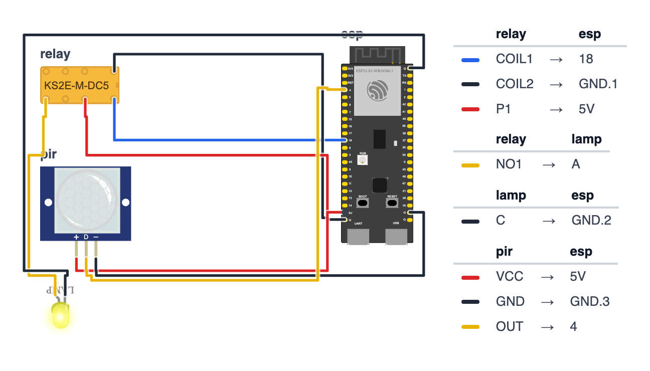
Relay Module (3 wires):
- Relay VCC → board 5V — red wire
- Relay GND → board GND — black wire
- Relay IN (signal) → board GPIO 18 (C6: GPIO 11) — blue wire
PIR Motion Sensor (3 wires): 4. PIR VCC → board 5V — red wire 5. PIR GND → board GND — black wire 6. PIR OUT → board GPIO 4 (C6: GPIO 0) — yellow wire
Check: Relay and PIR both get 5V. The PIR has a little voltage regulator inside and needs at least 4.5V to work properly. Don’t worry about the ESP32: the PIR’s OUT pin only ever sends 3.3V. Count: 6 wires total. Board not plugged into USB yet.
Check: The relay module has three terminals on its mains side — COM, NO, NC. Ignore those for now. You’re only wiring the low-voltage side (VCC, GND, IN).
Step 2: Flash the code
Time: ~10 minutes
Install Arduino IDE 2 with the ESP32 board package (see the quickstart guide if needed). Then upload this code with your WiFi credentials filled in:
The big picture first. This program turns the ESP32 into a smart light controller with three modes:
- Manual mode — you tap ON/OFF on a web page, relay clicks, light changes.
- Schedule mode — the ESP32 asks a time server what time it is and turns the light on at 8pm, off at 11pm, automatically.
- Motion mode — the PIR sensor turns the light on when someone walks by, and turns it off after 5 minutes of silence.
- A relay is an electrically controlled switch inside a plastic box. A small signal from the ESP32 closes the switch, which completes the lamp’s power circuit.
// ========== CHOOSE YOUR BOARD ==========
// Uncomment the line for YOUR board:
#define BOARD_S3 // ESP32-S3-DevKitC-1
//#define BOARD_C6 // ESP32-C6-DevKitC-1
// ========================================
#ifdef BOARD_S3
#define PIN_RELAY 18
#define PIN_PIR 4
#endif
#ifdef BOARD_C6
#define PIN_RELAY 11
#define PIN_PIR 0
#endif
#include <WiFi.h>
#include <WebServer.h>
#include <time.h>
const char* ssid = "YourWiFiName";
const char* password = "YourWiFiPassword";
int mode = 0;
bool relayOn = false;
unsigned long lastMotion = 0;
const unsigned long MOTION_TIMEOUT = 5 * 60 * 1000UL;
int scheduleOnHour = 20;
int scheduleOffHour = 23;
WebServer server(80);
void setRelay(bool on) {
relayOn = on;
digitalWrite(PIN_RELAY, on ? LOW : HIGH);
}
String getHTML() {
String modeLabel = (mode == 0) ? "Manual" : (mode == 1) ? "Schedule" : "Motion";
String stateLabel = relayOn ? "ON" : "OFF";
String stateColor = relayOn ? "#4caf50" : "#f44336";
return R"(<!DOCTYPE html><html><head>
<meta name="viewport" content="width=device-width,initial-scale=1">
<meta http-equiv="refresh" content="10">
<style>
body { font-family: sans-serif; text-align: center;
background: #1a1a2e; color: #eee; padding: 20px; }
h1 { color: #e94560; }
.state { font-size: 48px; font-weight: bold; color: )" + stateColor + R"(; }
.btn { display: inline-block; background: #16213e; border: 1px solid #0f3460;
color: white; padding: 14px 24px; margin: 8px; border-radius: 8px;
text-decoration: none; font-size: 15px; }
.active { background: #0f3460; border-color: #e94560; }
</style></head><body>
<h1>💡 Smart Light</h1>
<p class="state">)" + stateLabel + R"(</p>
<p>Mode: )" + modeLabel + R"(</p>
<hr>
<h3>Control</h3>
<a class="btn" href="/relay?state=on">Turn ON</a>
<a class="btn" href="/relay?state=off">Turn OFF</a>
<hr>
<h3>Mode</h3>
<a class="btn)" + (mode==0?" active":"") + R"(" href="/mode?m=0">Manual</a>
<a class="btn)" + (mode==1?" active":"") + R"(" href="/mode?m=1">Schedule</a>
<a class="btn)" + (mode==2?" active":"") + R"(" href="/mode?m=2">Motion</a>
</body></html>)";
}
void handleRoot() { server.send(200, "text/html", getHTML()); }
void handleRelay() {
if (server.hasArg("state")) setRelay(server.arg("state") == "on");
server.sendHeader("Location", "/"); server.send(303);
}
void handleMode() {
if (server.hasArg("m")) mode = server.arg("m").toInt();
server.sendHeader("Location", "/"); server.send(303);
}
void setup() {
Serial.begin(115200);
pinMode(PIN_RELAY, OUTPUT);
pinMode(PIN_PIR, INPUT);
setRelay(false);
WiFi.begin(ssid, password);
while (WiFi.status() != WL_CONNECTED) { delay(500); Serial.print("."); }
Serial.printf("\nIP: %s\n", WiFi.localIP().toString().c_str());
configTime(0, 0, "pool.ntp.org");
server.on("/", handleRoot);
server.on("/relay", handleRelay);
server.on("/mode", handleMode);
server.begin();
Serial.println("Smart light ready.");
}
void loop() {
server.handleClient();
if (mode == 1) {
struct tm timeinfo;
if (getLocalTime(&timeinfo)) {
int h = timeinfo.tm_hour;
bool shouldBeOn = (h >= scheduleOnHour && h < scheduleOffHour);
if (shouldBeOn != relayOn) setRelay(shouldBeOn);
}
delay(30000);
} else if (mode == 2) {
if (digitalRead(PIN_PIR) == HIGH) {
lastMotion = millis();
if (!relayOn) { setRelay(true); Serial.println("Motion — light ON"); }
}
if (relayOn && (millis() - lastMotion > MOTION_TIMEOUT)) {
setRelay(false); Serial.println("No motion — light OFF");
}
delay(500);
}
}Line-by-line: what every line does and why
Lines 1–3: Borrowing ready-made tools
#include <WiFi.h>
#include <WebServer.h>
#include <time.h>#include grabs instruction books. WiFi connects to your network. WebServer hosts the control web page. time.h provides the functions for reading the current time from an NTP (Network Time Protocol) server.
Lines 5–18: Settings
  #define PIN_RELAY  18
  #define PIN_PIR     4
int mode       = 0;
bool relayOn   = false;
unsigned long lastMotion = 0;
const unsigned long MOTION_TIMEOUT = 5 * 60 * 1000UL;
int scheduleOnHour  = 20;
int scheduleOffHour = 23;
#define PIN_RELAY 18 — GPIO 18 controls the relay’s signal wire, and PIN_PIR puts the PIR on GPIO 4. These lines come from the BOARD_S3 block at the top of the sketch; the C6 block uses GPIO 11 and GPIO 0. A #define name is locked — it never changes while the program runs.
int mode = 0 — int is a whole number. 0 = Manual, 1 = Schedule, 2 = Motion. This single number determines which behavior runs in loop().
bool relayOn = false — yes/no box for the relay state. Starts false (off).
unsigned long lastMotion = 0 — sticky note: “when did we last see motion?” Starts at 0 (never).
5 * 60 * 1000UL — calculate 5 minutes in milliseconds: 5 minutes × 60 seconds × 1,000 ms/second = 300,000. UL means “unsigned long” — needed because this number is too large for a regular int.
scheduleOnHour = 20 — 20 means 8pm in 24-hour format. scheduleOffHour = 23 means 11pm.
Lines 20–25: setRelay() — controls the lamp
void setRelay(bool on) {
  relayOn = on;
  digitalWrite(PIN_RELAY, on ? LOW : HIGH);
}
void setRelay(bool on) — a function that takes one yes/no argument.
on ? LOW : HIGH is a ternary operator — compact if/else. “If on is true, use LOW; otherwise use HIGH.”
Why LOW for ON? Most relay modules are active-LOW: they energize (close the switch) when you write LOW, and de-energize (open the switch) when you write HIGH. This seems backwards, but it’s a safety feature — if the GPIO pin is uninitialized (floating), it defaults to HIGH, so the relay stays OFF (safe). Writing LOW requires a deliberate action.
Lines 27–60: getHTML() — builds the web page
String getHTML() {
  String modeLabel  = (mode == 0) ? "Manual" : (mode == 1) ? "Schedule" : "Motion";
  String stateLabel = relayOn ? "ON" : "OFF";
  String stateColor = relayOn ? "#4caf50" : "#f44336";
  return R"(...)";
}
This function returns the complete HTML for the web page as a string. Every time you load the page, getHTML() runs and builds the page fresh with the current state.
The chained ternary: (mode == 0) ? "Manual" : (mode == 1) ? "Schedule" : "Motion" — three options in one line. Read it: “if 0 → Manual, if 1 → Schedule, otherwise → Motion.”
"#4caf50" is green (light is ON), "#f44336" is red (light is OFF) — hex color codes.
R"(...)" is a raw string literal — everything inside is taken literally, including line breaks and quotation marks. No need to escape characters. The web page HTML goes here.
Lines 62–72: Request handlers
void handleRoot()  { server.send(200, "text/html", getHTML()); }
void handleRelay() {
  if (server.hasArg("state")) setRelay(server.arg("state") == "on");
  server.sendHeader("Location", "/"); server.send(303);
}
void handleMode()  {
  if (server.hasArg("m")) mode = server.arg("m").toInt();
  server.sendHeader("Location", "/"); server.send(303);
}
These three functions handle the web routes:
server.send(200, "text/html", getHTML()) — send the HTML page. 200 is the HTTP success code.
server.arg("state") — reads the URL parameter. When you tap “Turn ON,” the browser goes to /relay?state=on. server.arg("state") returns "on".
server.arg("state") == "on" — this comparison returns true or false — directly passed to setRelay().
server.sendHeader("Location", "/") and server.send(303) — redirect back to the main page after the action. 303 is “See Other” — the standard HTTP redirect after a form action.
Lines 74–91: setup() — morning routine
setRelay(false) — start with the light OFF.
configTime(0, 0, "pool.ntp.org") — configure NTP time sync. The ESP32 has no internal clock battery — it gets the current time from pool.ntp.org (a global cluster of atomic clock servers, free to use). The first two 0, 0 arguments are timezone offset and daylight saving offset in seconds. For your local time, replace with your UTC offset: 3600 = UTC+1, 7200 = UTC+2, etc.
server.on("/relay", handleRelay) — “when the browser visits /relay, call handleRelay.”
Lines 93–116: loop() — three-mode behavior
void loop() {
  server.handleClient();

  if (mode == 1) {
    struct tm timeinfo;
    if (getLocalTime(&timeinfo)) {
      int h = timeinfo.tm_hour;
      bool shouldBeOn = (h >= scheduleOnHour && h < scheduleOffHour);
      if (shouldBeOn != relayOn) setRelay(shouldBeOn);
    }
    delay(30000);
  } else if (mode == 2) {
    if (digitalRead(PIN_PIR) == HIGH) {
      lastMotion = millis();
      if (!relayOn) setRelay(true);
    }
    if (relayOn && (millis() - lastMotion > MOTION_TIMEOUT)) {
      setRelay(false);
    }
    delay(500);
  }
}
server.handleClient() — check if any browser sent a request. Must be called continuously.
Schedule mode (mode == 1):
struct tm timeinfo— a time structure (like a form with fields: hour, minute, second, day…).getLocalTime(&timeinfo)— fill the form with the current time from NTP.timeinfo.tm_hour— read just the hour field (0–23).h >= scheduleOnHour && h < scheduleOffHour— is the current hour between 20 and 23?&&means AND — both conditions must be true.shouldBeOn != relayOn—!=means “not equal.” Only callsetRelay()if the desired state differs from the actual state.delay(30000)— check every 30 seconds. This blocks the web server for 30 seconds — fine for schedule mode where minute-level precision is enough.
Motion mode (mode == 2):
- PIR HIGH → record
lastMotion = millis()(update the “last motion” sticky note), turn light on if not already on. relayOn && (millis() - lastMotion > MOTION_TIMEOUT)— “is the light on AND has it been quiet for 5 minutes?” If both true, turn off.delay(500)— check twice per second.
The whole thing in one sentence
loop() continuously handles web requests and, depending on the mode variable, either waits for manual button taps, checks NTP time against the schedule, or watches the PIR sensor to control the relay.
First thing to try: start in Manual mode. Open the web page and tap “Turn ON.” Listen for the relay click. Tap “Turn OFF.” Then switch to Motion mode and walk in front of the PIR sensor — the relay should click on. Wait 5 minutes (or change MOTION_TIMEOUT to 10 * 1000UL for 10 seconds during testing).
Check: Open Serial Monitor (115200 baud). You should see “IP: 192.168.x.x” within 10 seconds. Open that IP in your browser. The web page should load showing “OFF” and “Manual” mode.
Step 3: Test the relay (before mains wiring)
Time: ~2 minutes
With just the ESP32 and relay connected (no lamp yet):
- Open the web page and tap “Turn ON”
- Listen for a click from the relay module — that’s the internal switch closing
- Tap “Turn OFF” — another click
- Try Schedule mode: set
scheduleOnHourto 1 hour before now andscheduleOffHourto 1 hour from now, re-upload, switch to Schedule mode — relay should click on
Check: You hear clicks. If not, check that relay VCC is on the 5V pin (the relay coil needs 5V, not 3.3V).
Step 4: Connect the lamp (mains wiring — adult required)
Time: ~10 minutes with an adult
Do this step only after the relay clicks correctly in Step 3. All mains work happens with the lamp unplugged from the wall.
- Unplugged lamp on a table — cord laid flat
- Identify the black/hot wire in the cord (in a standard two-wire lamp cord, the hot wire is the one on the side with the narrower prong)
- Cut the hot wire in the middle of the cord
- Connect one cut end to relay COM
- Connect the other cut end to relay NO
- Leave the white/neutral wire uncut — it bypasses the relay entirely
- Put all mains connections in a project box. No bare metal exposed.
- Plug the lamp into the wall, then power the ESP32 from a separate USB adapter
- Tap “Turn ON” on the web page — lamp lights up
- Tap “Turn OFF” — lamp goes out
Check: Lamp responds to ON/OFF from the web page. You’re done with hardware.
What just happened
You used some real home automation concepts:
-
Relay active-LOW logic trips everyone up the first time. Writing
LOWcloses the relay (lamp on). WritingHIGHopens it (lamp off). This is backwards from intuition — it’s called active-LOW because the relay activates on a low voltage signal. The hardware designers did it to prevent accidental activation from floating pins on boot. It’s a safety feature in inverted form. -
NTP time synchronization: Your ESP32 calls
configTime()to contactpool.ntp.org, one of the global atomic clock servers. From then on,getLocalTime()knows the current hour. The ESP32 has no battery-backed clock, so it needs WiFi to know what time it is. No WiFi = schedule mode stops working. That’s a real design constraint. -
PIR sensor physics: A PIR sensor doesn’t see people — it sees temperature differences moving across its field of view. When you walk past it, your body heat moves across the sensor’s detection zones and creates a voltage signal. The output goes HIGH for a few seconds, then LOW. That’s why the code tracks
lastMotion(the last time HIGH was seen) and measures elapsed time — not the duration of the HIGH pulse. -
Three-mode pattern: Manual → Schedule → Motion is a design pattern you’ll see in every real home automation product. Manual is always the fallback override. Schedule handles routine behavior. Motion adds intelligence. Using a
modevariable instead of nested if/else means adding a fourth mode (“vacation mode”) only changes one block of code.
Level Up
Add sunset/sunrise calculation. Instead of hardcoding scheduleOnHour = 20, look up a solar position algorithm based on your GPS coordinates. The sunset time shifts 2+ hours across the year. A real smart light follows the sun, not a fixed clock.
Add vacation mode. Create mode = 3 that turns the light on and off at random times within a 2-hour window (e.g., on between 7pm–9pm, off between 9pm–11pm). Use random() to pick a different time each day. This makes would-be burglars think someone is home — the randomness is the security feature.
Log to a Google Sheet. Every time setRelay() is called, send an HTTP POST to a Google Apps Script URL with the timestamp and new state. After a week you’ll have a chart showing exactly when your lights were on. Real data about your own house.
Troubleshooting
| Problem | Fix |
|---|---|
| Relay doesn’t click | Check relay VCC is on 5V (not 3.3V). The relay coil needs 5V. |
| Lamp doesn’t respond but relay clicks | Check COM and NO are connected (not NC). The lamp cord hot wire should go through COM → NO. |
| Schedule mode doesn’t work | The ESP32 needs active WiFi to sync time. Check WiFi is connected. Also: NTP uses UTC — set your timezone offset in configTime(offsetSeconds, dstSeconds, "pool.ntp.org"). |
| PIR triggers constantly | Move it away from heaters, sunny windows, and AC vents. Angle it downward slightly. PIR sensors need 30–60 seconds to “settle” after power-on — ignore the first minute. |
| Web page doesn’t load | Make sure your phone is on the same WiFi as the ESP32 (not mobile data). Try the IP address directly — don’t use a VPN. |