Parent info
Parts you need
Affiliate links — we may earn a small commission
Try this circuit in your browser!
Run the code, press the buttons and watch what happens — before you buy any parts. No account needed.
Open in Simulator →Your classmates dipped pH paper in water. You built a water quality analyzer.
Grade 8 chemistry: acids and bases, solutions, water quality. Everyone dips pH indicator paper into a glass of water, the paper turns some color, and they squint at a chart. “I think it’s 7?” That’s the state of the art in most 8th grade chem labs.
Your device has two sensors: a pH sensor that measures the exact acidity of any liquid to one decimal place, and a TDS sensor that measures total dissolved solids (how “dirty” or “mineral-rich” the water is) in parts per million. The OLED shows both readings with color-coded status. You can test tap water, river water, rain water, filtered water, and compare them all. Real environmental scientists use exactly this approach.
What you’ll need
| Part | What it does | Price |
|---|---|---|
| ESP32-S3-DevKitC-1 | The brain — reads two analog sensors and calculates quality scores | ~$12 |
| Analog pH sensor module | Measures how acidic or basic a solution is (0–14 scale) | ~$8 |
| TDS sensor module | Measures total dissolved solids in parts per million (ppm) | ~$7 |
| 0.96” OLED display | Shows readings with safe/unsafe status | ~$5 |
| Breadboard + jumper wires | Connects everything | ~$5 |
| 10kΩ + 20kΩ resistors | Turn the pH module’s 5V signal into a safe 3.3V | ~$1 |
Total: ~$38 | Time: ~2.5 hours | Difficulty: ●●●○○
What is TDS? Total Dissolved Solids measures how many minerals, salts, and other dissolved particles are in water. Tap water typically reads 50–500 ppm depending on your location. Pure distilled water = ~0 ppm. Ocean water = ~35,000 ppm. Safe drinking water per EPA guidelines: under 500 ppm.
How it works (60 seconds)
The pH sensor has a glass electrode probe that generates a tiny voltage based on the hydrogen ion concentration in the liquid. The ESP32 reads this voltage and converts it to a pH value using a calibration formula. The TDS sensor passes a small current through the water and measures resistance — more dissolved minerals = lower resistance = higher TDS reading. Both sensors output analog voltages that the ESP32 reads on its ADC (Analog-to-Digital Converter) pins. The code then compares readings to EPA water quality standards and displays a “safe” or “investigate” status.
Step 0: Plan your water quality experiment
Time: ~10 minutes
The best science fair project with this device compares multiple water sources:
| Sample | Expected pH | Expected TDS | Notes |
|---|---|---|---|
| Tap water | 6.5–8.5 | 50–500 ppm | Varies by city |
| Bottled water | 6.0–7.5 | 20–200 ppm | Mineral water = higher |
| Rainwater | 5.0–6.5 | 5–20 ppm | Slightly acidic (CO₂) |
| Soda water | 3.5–4.5 | 200–400 ppm | Carbonic acid |
| Baking soda water | 8.0–9.0 | 50–300 ppm | Basic |
| Lemon water | 2.5–3.5 | 50–100 ppm | Citric acid |
Your hypothesis: “Tap water from [location] will meet EPA drinking water standards (pH 6.5–8.5, TDS < 500 ppm).” Test and find out.
Safety note: Only test water that’s safe to handle. Don’t test bleach, strong acids, or household chemicals. Citric acid from lemon juice or baking soda solutions are the strongest things you need for a school experiment.
Step 1: Wire it up
Time: ~15 minutes
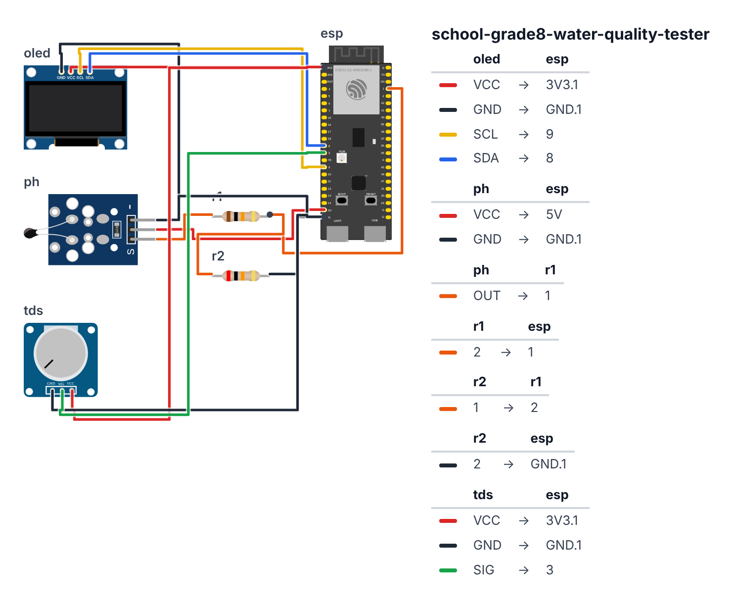
OLED Display (I2C):
- OLED VCC → board 3.3V — red wire
- OLED GND → board GND — black wire
- OLED SCL → board GPIO 9 (C6: GPIO 7) — yellow wire
- OLED SDA → board GPIO 8 (C6: GPIO 6) — blue wire
pH Sensor Module (analog output): 5. pH module VCC → board 5V — red wire 6. pH module GND → board GND — black wire 7. pH module Po (analog output) → 10kΩ resistor → board GPIO 1 — orange wire 8. 20kΩ resistor from board GPIO 1 → GND — so the module’s 5V signal becomes a safe 3.3V
TDS Sensor Module (analog output): 9. TDS sensor VCC → board 3.3V — red wire 10. TDS sensor GND → board GND — black wire 11. TDS sensor AOUT → board GPIO 3 (C6: GPIO 2) — green wire
Check: GPIO 1 and GPIO 3 (C6: GPIO 1 and GPIO 2) are ADC-capable pins — perfect for reading analog sensors. The pH module needs a 5V supply for the op-amp inside, so its signal can go up to 5V — the two resistors (steps 7–8) bring it down to 3.3V, the most an ESP32 pin can take. The TDS sensor works on 3.3V.
Step 2: Flash the code
Time: ~25 minutes
Install Adafruit SSD1306 and Adafruit GFX libraries.
Think of this code as a chemistry lab assistant that never makes mistakes reading the instruments. A real lab assistant would dip a probe, wait for it to settle, write down the voltage, consult a conversion chart to get pH, then check a reference guide to say whether it is safe — and they would do all of this 30 times per reading and average the results to cancel out shaky-hand errors. That is exactly what this code does, automatically, every 5 seconds. The pH sensor works like a tiny battery whose voltage changes depending on how acidic the liquid is — more acid means more hydrogen ions, which changes a chemical reaction inside the glass probe tip, which changes the voltage the probe pushes out. The TDS sensor works differently: it measures how easily electricity flows through the water — more dissolved minerals means more conductors means electricity flows more easily. Both sensors produce voltages; the code converts those voltages into the numbers chemists actually use.
// ========== CHOOSE YOUR BOARD ==========
// Uncomment the line for YOUR board:
#define BOARD_S3    // ESP32-S3-DevKitC-1
//#define BOARD_C6  // ESP32-C6-DevKitC-1
// ========================================

#ifdef BOARD_S3
  #define PIN_SDA   8
  #define PIN_SCL   9
  #define PIN_PH    1
  #define PIN_TDS   3
#endif
#ifdef BOARD_C6
  #define PIN_SDA   6
  #define PIN_SCL   7
  #define PIN_PH    1
  #define PIN_TDS   2
#endif

#include <Wire.h>
#include <Adafruit_SSD1306.h>

#define SCREEN_WIDTH 128
#define SCREEN_HEIGHT 64
Adafruit_SSD1306 display(SCREEN_WIDTH, SCREEN_HEIGHT, &Wire, -1);

float PH_OFFSET = 0.0;
float PH_SLOPE  = 3.5;

float TDS_VREF = 3.3;
float TDS_K = 500.0;

#define SAMPLES 30

float readVoltage(int pin) {
  long sum = 0;
  for (int i = 0; i < SAMPLES; i++) {
    sum += analogRead(pin);
    delay(2);
  }
  float avgRaw = (float)sum / SAMPLES;
  return avgRaw / 4095.0 * 3.3;
}

float voltageToPH(float voltage) {
  float ph = 7.0 + (2.5 - voltage) / 0.18 + PH_OFFSET;
  return constrain(ph, 0.0, 14.0);
}

float voltageToPPM(float voltage) {
  float ppm = (voltage / TDS_VREF) * TDS_K * 1000.0;
  return constrain(ppm, 0, 5000);
}

String assessPH(float ph) {
  if (ph >= 6.5 && ph <= 8.5) return "SAFE";
  if (ph >= 6.0 && ph < 6.5) return "MILDLY ACID";
  if (ph > 8.5 && ph <= 9.5) return "MILDLY BASE";
  if (ph < 6.0) return "TOO ACIDIC";
  return "TOO BASIC";
}

String assessTDS(float ppm) {
  if (ppm < 300) return "EXCELLENT";
  if (ppm < 600) return "GOOD";
  if (ppm < 900) return "FAIR";
  if (ppm < 1200) return "POOR";
  return "UNSAFE";
}

int logCount = 0;

void takeAndDisplayReading() {
  float phVoltage = readVoltage(PIN_PH);
  float tdsVoltage = readVoltage(PIN_TDS);

  float ph = voltageToPH(phVoltage);
  float ppm = voltageToPPM(tdsVoltage);

  String phStatus = assessPH(ph);
  String tdsStatus = assessTDS(ppm);

  logCount++;

  Serial.print(logCount); Serial.print(",");
  Serial.print(phVoltage, 4); Serial.print(",");
  Serial.print(ph, 2); Serial.print(",");
  Serial.print(tdsVoltage, 4); Serial.print(",");
  Serial.print(ppm, 0); Serial.print(",");
  Serial.print(phStatus); Serial.print(",");
  Serial.println(tdsStatus);

  display.clearDisplay();
  display.setTextColor(SSD1306_WHITE);

  display.setTextSize(1);
  display.setCursor(0, 0);
  display.println("WATER QUALITY TEST");
  display.drawLine(0, 9, 128, 9, SSD1306_WHITE);

  display.setCursor(0, 12);
  display.print("pH: ");
  display.setTextSize(2);
  display.print(ph, 1);
  display.setTextSize(1);
  display.print("  ");
  display.print("[");
  display.print(phStatus.substring(0, 6));
  display.println("]");

  display.setTextSize(1);
  display.setCursor(0, 32);
  display.print("TDS: ");
  display.print(ppm, 0);
  display.print(" ppm [");
  display.print(tdsStatus.substring(0, 5));
  display.println("]");

  display.setCursor(0, 48);
  bool overallSafe = (phStatus == "SAFE") && (tdsStatus != "UNSAFE");
  if (overallSafe) {
    display.println("VERDICT: SAFE TO DRINK");
  } else {
    display.println("VERDICT: INVESTIGATE!");
  }

  display.setCursor(0, 56);
  display.print("Reading #"); display.print(logCount);

  display.display();
}

void setup() {
  Serial.begin(115200);
  Wire.begin(PIN_SDA, PIN_SCL);

  if (!display.begin(SSD1306_SWITCHCAPVCC, 0x3C)) {
    while (true);
  }

  display.clearDisplay();
  display.setTextColor(SSD1306_WHITE);
  display.setCursor(0, 0);
  display.println("Water Quality");
  display.println("Analyzer v1.0");
  display.println();
  display.println("Warming up...");
  display.display();
  delay(3000);

  Serial.println("Water Quality Tester Ready");
  Serial.println("Reading#,pH_Voltage,pH,TDS_Voltage,TDS_ppm,pH_Status,TDS_Status");
}

unsigned long lastReading = 0;

void loop() {
  unsigned long now = millis();

  if (now - lastReading >= 5000) {
    takeAndDisplayReading();
    lastReading = now;
  }
}
Line-by-line: what every line does and why
Sensor pin definitions
#define PIN_PH 1 and #define PIN_TDS 3 — both sensors connect to ADC (Analog-to-Digital Converter) pins. GPIO 1 and GPIO 3 on the ESP32-S3 (C6: GPIO 1 and GPIO 2) are ADC-capable pins — they can read voltages between 0 V and 3.3 V and convert them to numbers from 0 to 4095. #define gives a human-readable name to a pin number so you never confuse which sensor is which.
Calibration constants
float PH_OFFSET = 0.0; — a correction you can add to shift all pH readings up or down. If your probe reads 7.3 in pH 7.0 buffer solution, set PH_OFFSET = -0.3 and the math auto-corrects.
float PH_SLOPE = 3.5; — used in the conversion formula. The default 0.18 in voltageToPH() is a theoretical slope. PH_SLOPE is available if you want to replace the theoretical slope with one measured from your own probe.
float TDS_VREF = 3.3; — the maximum voltage the ADC can read (3.3 V on ESP32). Used to normalize the TDS voltage into a 0–1 fraction.
float TDS_K = 500.0; — a scaling constant for the TDS module. Different TDS modules have different calibrations. The default 500 is a starting guess; calibrate with distilled water (should read near 0 ppm) and tap water (should read 50–500 ppm).
readVoltage() — averaging 30 samples
float readVoltage(int pin) {
  long sum = 0;
  for (int i = 0; i < SAMPLES; i++) {
    sum += analogRead(pin);
    delay(2);
  }
  float avgRaw = (float)sum / SAMPLES;
  return avgRaw / 4095.0 * 3.3;
}
long sum = 0; — long is a large whole number (up to ~2 billion). We need long because 30 samples × 4095 max = 122,850, which is larger than what a regular int (max ~32,767) can hold.
for (int i = 0; i < SAMPLES; i++) — loops 30 times (SAMPLES = 30). Each loop, analogRead(pin) reads the ADC once and adds its value to sum. delay(2) waits 2 milliseconds between reads — the ADC capacitor needs a moment to fully charge between samples.
float avgRaw = (float)sum / SAMPLES; — divides the total by 30 to get the average. The (float) cast converts sum from a whole number to a decimal number before dividing, so 122850 / 30 gives 4095.0 instead of 4095 (which would lose the decimal precision).
return avgRaw / 4095.0 * 3.3; — converts the 0–4095 ADC reading to a 0–3.3 V voltage. Division by 4095 gives a 0–1 fraction, multiplied by 3.3 gives actual volts. Result: a stable voltage reading with noise reduced by averaging.
voltageToPH() — the Nernst equation in code
float ph = 7.0 + (2.5 - voltage) / 0.18 + PH_OFFSET;
return constrain(ph, 0.0, 14.0);
7.0 + (2.5 - voltage) / 0.18 — this is based on the Nernst equation, the fundamental formula of electrochemistry. Key fact: most pH probes output exactly 2.5 V at pH 7 (neutral). Every 0.18 V change corresponds to 1 pH unit (59 mV from the Nernst equation, divided by the sensor’s internal voltage divider ratio ≈ 0.18 V/pH).
If voltage = 2.5: (2.5 - 2.5) / 0.18 = 0 → pH = 7 (neutral). Correct.
If voltage = 2.32 (lower): (2.5 - 2.32) / 0.18 = 1.0 → pH = 8 (basic). More basic = lower voltage.
If voltage = 2.68 (higher): (2.5 - 2.68) / 0.18 = -1.0 → pH = 6 (acidic). More acidic = higher voltage.
+ PH_OFFSET — adds your calibration correction on top.
constrain(ph, 0.0, 14.0) — the pH scale only runs from 0 to 14. This prevents impossible values (like pH 15 or pH -2) from appearing if the sensor is in air or badly calibrated.
voltageToPPM() — TDS conversion
float ppm = (voltage / TDS_VREF) * TDS_K * 1000.0; — converts voltage to parts per million. Breaking it down:
voltage / TDS_VREF= a 0–1 fraction of the full voltage range× TDS_K= scales by the calibration constant (500 by default)× 1000.0= converts from “thousands of ppm” to actual ppm
constrain(ppm, 0, 5000) — clamps the result to 0–5,000 ppm. Ocean water is ~35,000 ppm; for this device anything over 5,000 is “off the chart.”
assessPH() and assessTDS() — EPA lookup tables in code
String assessPH(float ph) {
  if (ph >= 6.5 && ph <= 8.5) return "SAFE";
  if (ph >= 6.0 && ph < 6.5) return "MILDLY ACID";
  ...
}
String is a text value (words, not numbers). return "SAFE" sends the word “SAFE” back to whoever called the function. The && means “AND” — both conditions must be true. ph >= 6.5 && ph <= 8.5 means “pH is at least 6.5 AND at most 8.5” — which is the EPA drinking water range.
The if statements are checked from top to bottom. The first one that matches wins. If pH is 7.0, the first check (>= 6.5 && <= 8.5) matches immediately and returns “SAFE” — the other checks are skipped.
assessTDS() works the same way for TDS: EXCELLENT (< 300 ppm), GOOD (< 600), FAIR (< 900), POOR (< 1200), UNSAFE (anything higher).
takeAndDisplayReading() — the main measurement function
float phVoltage = readVoltage(PIN_PH); — calls readVoltage() on the pH pin. This triggers 30 analog reads, averages them, and returns a voltage in volts (e.g., 2.47 V).
float ph = voltageToPH(phVoltage); — passes that voltage through the Nernst formula to get a pH value (e.g., 7.2).
String phStatus = assessPH(ph); — checks the EPA table and returns a word like “SAFE”.
logCount++; — increments the reading counter. The ++ operator adds 1. So if logCount was 5, it becomes 6.
Serial logging: Serial.print(logCount); Serial.print(","); — prints comma-separated values one field at a time. This creates CSV (comma-separated values) format that can be pasted directly into Excel or Google Sheets to build a comparison table.
Display layout:
display.setTextSize(2); for the pH number — bigger font (16 pixels tall instead of 8) so the numeric reading is easy to read from across the room.
phStatus.substring(0, 6) — takes only the first 6 characters of the status string. This prevents long labels like “MILDLY ACID” from overflowing the screen edge.
bool overallSafe = (phStatus == "SAFE") && (tdsStatus != "UNSAFE"); — calculates the overall verdict. The == checks if two strings are identical. The != checks if they are NOT equal. Both pH must be SAFE and TDS must not be UNSAFE for the overall verdict to be positive.
setup() — sensor warm-up
delay(3000) — waits 3 seconds after boot. Analog pH sensors have glass electrodes that need time to stabilize — the first reading immediately after power-on is unreliable. Three seconds of “Warming up…” gives the electrochemistry inside the probe time to settle.
Serial.println("Reading#,pH_Voltage,pH,TDS_Voltage,TDS_ppm,pH_Status,TDS_Status"); — prints a header row for the CSV log. This appears once at boot so the Serial Monitor data is always labeled — you can copy the whole thing and import it directly into a spreadsheet.
loop() — reading every 5 seconds
if (now - lastReading >= 5000) — waits 5 seconds between readings. This is essential because: (1) the ADC averaging inside readVoltage() takes 30 × 2ms = 60ms per sensor, so rushing doesn’t help; (2) the pH electrode needs a few seconds in new liquid before it stabilizes. Taking readings faster than 5 seconds would waste power and produce noisier data.
lastReading = now; — resets the timer. Next trigger: in exactly 5 more seconds.
The whole thing in one sentence: Every 5 seconds the code averages 30 ADC samples from each sensor, converts the average voltage to pH and TDS using calibration formulas, compares the results to EPA guidelines, and displays a color-coded verdict — while logging everything in CSV format for your data table.
First thing to try: Put both probes in a glass of tap water, open Serial Monitor, and watch the readings appear every 5 seconds — you should see pH somewhere between 6.5 and 8.5 and TDS in the 50–500 ppm range depending on your city.
Check: Open Serial Monitor. You should see voltage readings every 5 seconds. With the probes in open air (no water), they’ll give garbage readings — that’s normal. Put them in plain tap water and the pH should read somewhere between 6–8. The TDS should show a few hundred ppm.
Step 3: Calibrate your pH sensor
Time: ~15 minutes
pH sensors MUST be calibrated. Without calibration, the readings could be off by 1–2 pH units.
What you need for calibration:
- pH 7.0 buffer solution (comes with most pH sensor kits, or make it: distilled water is approximately pH 7)
- Optionally: pH 4.0 buffer solution (vinegar is approximately pH 4.5)
Two-point calibration:
- Put probe in your pH 7.0 buffer. Note the raw voltage from Serial Monitor.
- Put probe in your pH 4.0 solution. Note the voltage.
- Calculate slope:
slope = (voltage_at_4 - voltage_at_7) / (4.0 - 7.0) - Calculate offset:
offset = 7.0 - voltage_at_7 / slope - Update
PH_SLOPEandPH_OFFSETin the code with these values.
For a quick single-point calibration: use tap water (pH ~7.2 in most US cities) and adjust PH_OFFSET until the reading matches.
Step 4: Test your water samples
Rinse the probes with distilled water between samples. Put both probes in each water sample for 30 seconds. Record the reading. Move on to the next sample.
Always rinse between tests — contamination from a previous sample will affect the next reading.
What just happened
Chemistry concepts you used:
- pH scale — logarithmic measure of hydrogen ion concentration. pH 7 = neutral. Below 7 = acidic (more H⁺ ions). Above 7 = basic (more OH⁻ ions). Each whole number = 10× more acidic or basic.
- Nernst equation — the theoretical basis for pH electrodes. The electrode potential changes by 59.16mV per pH unit at 25°C. This is fundamental electrochemistry.
- Total Dissolved Solids — minerals naturally present in water affect its taste, conductivity, and safety. High TDS can indicate agricultural runoff, industrial contamination, or naturally mineral-rich groundwater.
- Sensor calibration — analog sensors have manufacturing variation. Calibration corrects for this. This is a universal step in any real laboratory measurement.
Curriculum alignment: NGSS MS-PS1-2 (Analyze and interpret data on the properties of substances before and after the substances interact to determine if a chemical reaction has occurred). Also MS-ESS3-3 (Apply scientific principles to design a method for monitoring and minimizing a human impact on the environment).
Presentation tip: Bring 5–6 labeled water samples to your presentation. Live-test one sample on stage and explain each reading as it appears. Then reveal your pre-collected comparison table. Ask your class: “Which water source had the highest TDS? Why might that be?” The discussion about where those dissolved solids come from is the whole point of the experiment.
Level Up
Temperature compensation: pH readings change with temperature (Nernst equation is temperature-dependent). Add a temperature sensor (DS18B20) in the water and apply temperature correction to your pH calculation.
Multiple sample logging: Add an SD card module. Create a new CSV file for each “session” (water quality test run). Build a record of samples over time and look for trends.
EPA comparison chart: Add code that compares your readings to EPA primary and secondary drinking water standards and displays exactly which standards are met or violated.
★★ You completed: Grade 8 Water Quality Tester!
Troubleshooting
| Problem | Fix |
|---|---|
| pH reads wildly wrong | Calibrate using known solutions (Step 3). pH sensors NEED calibration. |
| pH probe reading drifts constantly | Normal — pH electrodes need 30 seconds to stabilize in new solution. Wait before recording. |
| TDS reads 0 or very low | Check 3.3V on TDS module. Adjust TDS_K constant (try 200–1000 range). |
| Readings jump around a lot | Using 30 samples average helps. Make sure probes are fully submerged and not touching the container walls. |
| pH module needs 5V but ESP32 ADC is 3.3V | That’s what the 10kΩ + 20kΩ resistors in Step 1 are for: they turn the module’s 0–5V signal into 0–3.3V. Check they are wired exactly as in steps 7–8, then calibrate again (Step 3). |