Parent info
Parts you need
Affiliate links — we may earn a small commission
Try this circuit in your browser!
Run the code, press the buttons and watch what happens — before you buy any parts. No account needed.
Open in Simulator →Your classmates held a thermometer. You built a 3-sensor data system.
Grade 7 physical science: heat transfer. Conduction (heat through a solid), convection (heat through a fluid like air or water), radiation (heat through empty space). Your class puts three thermometers in three different places, waits a minute, reads the numbers, and argues about who read it wrong.
You have three DS18B20 digital temperature sensors — each on a different wire, all connected to the same ESP32. They update simultaneously every second. The OLED displays all three readings at once with bar graphs showing relative temperatures. You don’t read numbers once — you watch temperatures change in real time as heat moves through each medium.
That’s what a real heat transfer experiment looks like.
What you’ll need
| Part | What it does | Price |
|---|---|---|
| ESP32-S3-DevKitC-1 | The brain — reads all three sensors simultaneously | ~$12 |
| DS18B20 waterproof temp sensors (3-pack) | Digital temperature sensors on wire probes. Accurate to ±0.5°C. Can all share one data wire. | ~$8 |
| 0.96” OLED display | Shows all three temperatures simultaneously | ~$5 |
| 4.7kΩ resistor | Required pull-up resistor for the 1-Wire sensor bus | ~$3 |
| Breadboard + jumper wires | Connects everything | ~$5 |
Total: ~$33 | Time: ~2 hours | Difficulty: ●●●○○
What makes DS18B20 special? These sensors use a protocol called “1-Wire” — all three sensors share a single data wire. Each sensor has a unique 64-bit ID burned in at the factory, so the ESP32 can tell them apart even though they’re on the same wire. This is called device addressing and it’s used in many industrial sensor networks.
How it works (60 seconds)
The ESP32 sends a signal down one wire. Each DS18B20 sensor hears the signal and replies with its unique ID and temperature reading. The ESP32 matches the IDs to Sensor 1, 2, and 3 and displays all three. Because they’re all digital, all three read at the same time — no waiting for mercury to rise or arguing about which thermometer read first.
Step 0: Design your heat transfer experiment
Time: ~10 minutes
You need three different heat transfer setups. Here are the classic options:
Conduction test:
- Sensor 1: Probe touches the warm end of a metal rod (spoon, nail, wire)
- Let the other end of the rod touch something warm (warm water cup)
- Watch heat travel down the rod to Sensor 1
Convection test:
- Sensor 2: Probe in warm water
- Put the probe near the top of the water vs. near the bottom
- Hot water rises (convection currents) — the top should be warmer
Radiation test:
- Sensor 3: Probe hanging in air, facing a lamp or heat source
- No contact, no fluid — heat travels as infrared light through air
- Compare: Sensor 3 facing the lamp vs. turned away
A better experimental design: Start with all three sensors at room temperature. Then introduce heat to each setup simultaneously and record how fast each sensor rises. Rate of temperature change = key data point.
Step 1: Wire it up
Time: ~15 minutes
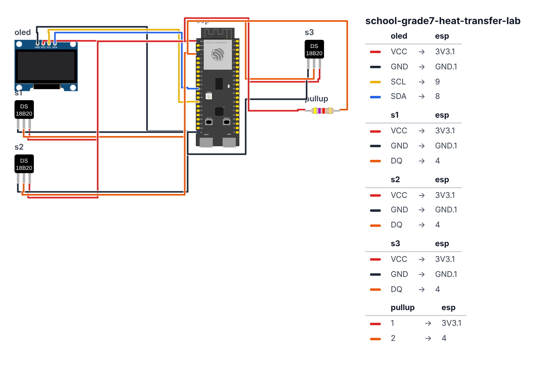
All three DS18B20 sensors share ONE data wire. This is the magic of the 1-Wire protocol.
All three DS18B20 sensors (parallel on one data bus):
- All three sensor RED wires → board 3.3V — red rail on breadboard
- All three sensor BLACK wires → board GND — black rail on breadboard
- All three sensor YELLOW/WHITE wires → board GPIO 4 (C6: GPIO 0) — data bus
- 4.7kΩ resistor between 3.3V and GPIO 4 (C6: GPIO 0) — this is the pull-up resistor, required!
OLED Display (I2C): 5. OLED VCC → board 3.3V 6. OLED GND → board GND 7. OLED SCL → board GPIO 9 (C6: GPIO 7) 8. OLED SDA → board GPIO 8 (C6: GPIO 6)
Check: All yellow/white data wires join together at GPIO 4 (C6: GPIO 0), with the 4.7kΩ resistor also connected there. This single wire carries data from all three sensors. Without the resistor, the sensors won’t respond.
Step 2: Flash the code
Time: ~25 minutes
Install these libraries in Arduino IDE:
OneWireby Jim StudtDallasTemperatureby Miles BurtonAdafruit SSD1306by AdafruitAdafruit GFX Libraryby Adafruit
Here is the big picture. This program reads three temperature sensors at the same time, all on one wire:
- The DS18B20 sensors are like three thermometers on a single chain. They share one data wire but each has a unique ID burned into it at the factory — like a phone number. The ESP32 calls each one by its ID and reads its temperature.
- 1-Wire protocol: the ESP32 talks down one wire, each sensor hears its name and answers with its temperature. It’s like calling attendance in a class.
- The OLED shows all three temperatures and a mini bar chart so you can compare them at a glance.
// ========== CHOOSE YOUR BOARD ==========
// Uncomment the line for YOUR board:
#define BOARD_S3    // ESP32-S3-DevKitC-1
//#define BOARD_C6  // ESP32-C6-DevKitC-1
// ========================================

#ifdef BOARD_S3
  #define PIN_SDA       8
  #define PIN_SCL       9
  #define PIN_ONEWIRE   4
#endif
#ifdef BOARD_C6
  #define PIN_SDA       6
  #define PIN_SCL       7
  #define PIN_ONEWIRE   0
#endif

#include <Wire.h>
#include <OneWire.h>
#include <DallasTemperature.h>
#include <Adafruit_SSD1306.h>

#define SCREEN_WIDTH 128
#define SCREEN_HEIGHT 64
Adafruit_SSD1306 display(SCREEN_WIDTH, SCREEN_HEIGHT, &Wire, -1);

#define ONE_WIRE_BUS PIN_ONEWIRE
OneWire oneWire(ONE_WIRE_BUS);
DallasTemperature sensors(&oneWire);

DeviceAddress sensor1Addr, sensor2Addr, sensor3Addr;
int foundSensors = 0;

const char* sensorLabels[3] = {"CONDUCT", "CONVECT", "RADIAT"};

#define HISTORY_SIZE 60
float sensorHistory[3][HISTORY_SIZE];
int historyIndex = 0;
int readingCount = 0;

void setup() {
  Serial.begin(115200);
  Wire.begin(PIN_SDA, PIN_SCL);

  if (!display.begin(SSD1306_SWITCHCAPVCC, 0x3C)) {
    Serial.println("Display not found!");
    while (true);
  }

  sensors.begin();
  foundSensors = sensors.getDeviceCount();

  display.clearDisplay();
  display.setTextColor(SSD1306_WHITE);
  display.setTextSize(1);
  display.setCursor(0, 0);
  display.print("Found "); display.print(foundSensors); display.println(" sensors");
  display.display();

  Serial.print("Found "); Serial.print(foundSensors); Serial.println(" DS18B20 sensors");

  if (foundSensors >= 1) sensors.getAddress(sensor1Addr, 0);
  if (foundSensors >= 2) sensors.getAddress(sensor2Addr, 1);
  if (foundSensors >= 3) sensors.getAddress(sensor3Addr, 2);

  Serial.println("Sensor addresses:");
  for (int i = 0; i < foundSensors; i++) {
    DeviceAddress addr;
    sensors.getAddress(addr, i);
    Serial.print("Sensor "); Serial.print(i+1); Serial.print(": ");
    for (int j = 0; j < 8; j++) {
      if (addr[j] < 16) Serial.print("0");
      Serial.print(addr[j], HEX);
      if (j < 7) Serial.print(":");
    }
    Serial.println();
  }

  delay(2000);
  Serial.println("Reading#,Conduction(C),Convection(C),Radiation(C)");
}

void updateDisplay(float t1, float t2, float t3) {
  display.clearDisplay();
  display.setTextColor(SSD1306_WHITE);

  display.setTextSize(1);
  display.setCursor(0, 0);
  display.println("HEAT TRANSFER LAB");
  display.drawLine(0, 9, 128, 9, SSD1306_WHITE);

  const char* labels[3] = {"CONDUCT:", "CONVECT:", "RADIAT: "};
  float temps[3] = {t1, t2, t3};

  for (int i = 0; i < 3; i++) {
    int y = 12 + (i * 16);
    display.setCursor(0, y);
    display.print(labels[i]);

    if (temps[i] == -127) {
      display.println("N/A");
    } else {
      display.setTextSize(1);
      display.print(temps[i], 1);
      display.println("C");

      int barWidth = (int)(temps[i] / 50.0 * 50);
      barWidth = constrain(barWidth, 0, 50);
      display.fillRect(78, y, barWidth, 8, SSD1306_WHITE);
    }
  }

  display.setCursor(0, 56);
  display.print("Readings: "); display.print(readingCount);

  display.display();
}

void loop() {
  sensors.requestTemperatures();

  float t1 = -127, t2 = -127, t3 = -127;

  if (foundSensors >= 1) t1 = sensors.getTempC(sensor1Addr);
  if (foundSensors >= 2) t2 = sensors.getTempC(sensor2Addr);
  if (foundSensors >= 3) t3 = sensors.getTempC(sensor3Addr);

  if (t1 != -127) sensorHistory[0][historyIndex % HISTORY_SIZE] = t1;
  if (t2 != -127) sensorHistory[1][historyIndex % HISTORY_SIZE] = t2;
  if (t3 != -127) sensorHistory[2][historyIndex % HISTORY_SIZE] = t3;

  historyIndex++;
  readingCount++;

  Serial.print(readingCount); Serial.print(",");
  Serial.print(t1, 2); Serial.print(",");
  Serial.print(t2, 2); Serial.print(",");
  Serial.println(t3, 2);

  updateDisplay(t1, t2, t3);

  delay(1000);
}
Line-by-line: what every line does and why
Lines 1–4: Borrowing four instruction books
#include <Wire.h>
#include <OneWire.h>
#include <DallasTemperature.h>
#include <Adafruit_SSD1306.h>
Four instruction books: I2C communication, the 1-Wire protocol (the chain-of-sensors system), the DS18B20 temperature sensor specifically, and the display.
Lines 10–12: Setting up the sensor chain
#define ONE_WIRE_BUS PIN_ONEWIRE
OneWire oneWire(ONE_WIRE_BUS);
DallasTemperature sensors(&oneWire);
All three DS18B20 sensors share pin 4 (C6: pin 0) as their common data wire — that’s the “one wire bus.” OneWire oneWire(ONE_WIRE_BUS) creates the communication channel. DallasTemperature sensors(&oneWire) builds the temperature library on top of it. Think of it as: OneWire is the road, DallasTemperature is the car driving on it.
Lines 14–16: Sensor address storage
DeviceAddress sensor1Addr, sensor2Addr, sensor3Addr;
int foundSensors = 0;
Each DS18B20 has a unique 8-byte ID burned in at the factory. DeviceAddress is a container that holds one such ID. We create three containers — one for each sensor. foundSensors counts how many sensors actually responded when we scanned the wire.
Line 18: Labels for your experiment
const char* sensorLabels[3] = {"CONDUCT", "CONVECT", "RADIAT"};A shelf of three text labels. const char* means “a pointer to text that won’t change.” These label which sensor measures what — rename them if your experiment uses different setups.
Lines 20–23: Data history
#define HISTORY_SIZE 60
float sensorHistory[3][HISTORY_SIZE];
This is a 2D shelf — like a spreadsheet with 3 rows and 60 columns. Row 0 = sensor 1’s last 60 readings, row 1 = sensor 2’s, row 2 = sensor 3’s. sensorHistory[0][5] is sensor 1’s 6th reading.
Lines 25–55: setup() — startup and sensor discovery
sensors.begin();
foundSensors = sensors.getDeviceCount();
sensors.begin() scans the 1-Wire bus and finds everyone on it. getDeviceCount() returns how many responded — should be 3.
if (foundSensors >= 1) sensors.getAddress(sensor1Addr, 0);
if (foundSensors >= 2) sensors.getAddress(sensor2Addr, 1);
if (foundSensors >= 3) sensors.getAddress(sensor3Addr, 2);
getAddress(addr, 0) reads the unique ID of the first sensor found and stores it in sensor1Addr. Later, we use this ID to read from that specific sensor — like calling someone by name instead of shouting in a crowd.
The Serial loop then prints all the sensor addresses — copy these to your lab notebook so you know which address belongs to which physical wire.
Lines 57–86: updateDisplay() — the three-sensor dashboard
for (int i = 0; i < 3; i++) {
  int y = 12 + (i * 16);
  ...
}
A for loop draws all three sensor readings. Each is placed 16 pixels lower than the previous one (i * 16). The bar chart (display.fillRect(78, y, barWidth, 8, SSD1306_WHITE)) draws a horizontal bar proportional to the temperature — wider bar = warmer.
if (temps[i] == -127) {
  display.println("N/A");
}
-127 is the DS18B20’s special error code — it returns this when a reading fails (usually a wiring problem). If we see it, show “N/A” instead of a nonsense temperature.
Lines 88–110: loop() — reading all three every second
sensors.requestTemperatures();This one command tells ALL sensors on the wire to start measuring simultaneously. Think of it as announcing “Attention everyone, take a reading now!” All three sensors measure at the same moment.
if (foundSensors >= 1) t1 = sensors.getTempC(sensor1Addr);Then we collect each answer individually by calling each sensor by its address. If the sensor wasn’t found during setup, we skip it (the if foundSensors >= N guard).
if (t1 != -127) sensorHistory[0][historyIndex % HISTORY_SIZE] = t1;Only store valid readings. historyIndex % HISTORY_SIZE wraps around after 60, making the buffer circular.
The whole thing in one sentence
At startup, the system discovers all three sensors and learns their unique addresses. Then it repeatedly requests all three temperatures at once, shows them on screen with comparison bars, and logs them to Serial.
First thing to try: Power on and open Serial Monitor. All three sensors should read near room temperature (20–23°C). Hold one sensor tightly in your fist for 30 seconds — body temperature is ~37°C. Watch that sensor climb while the others stay still.
Check: Open Serial Monitor. You should see three temperature columns updating every second. All three should start near room temperature (~20–22°C). If a sensor reads -127, check its wiring. Note down which sensor index matches which physical wire by reading the addresses printed at startup.
Step 3: Run the experiment
Time: 15–30 minutes
Start the experiment with all three sensors at room temperature (let them stabilize for 2 minutes first). Then:
- Set up your conduction setup (Sensor 1 touching warm metal)
- Put Sensor 2 in warm water
- Put Sensor 3 near a lamp (not touching anything)
Watch the OLED or Serial Monitor. You should see all three temperatures rise, but at different rates. Conduction through metal is typically fastest. Radiation is slower but continuous.
Record these key data points:
- Starting temperature (all three should be similar — room temp)
- Temperature at 1 minute, 2 minutes, 5 minutes
- Final stabilized temperature
Rate of change = (final temp - starting temp) / time in minutes. Which heat transfer method was fastest?
What just happened
Concepts you used:
- 1-Wire protocol — all three sensors share one wire. Each has a unique address. The bus master (ESP32) talks to them one at a time by addressing them individually. This is how many industrial sensor networks work.
- Digital vs. analog sensors — unlike a glass thermometer, these give exact digital numbers. No estimation, no parallax error, no waiting for mercury.
- Rate of change — the most interesting measurement is not the final temperature but how fast it changed. Rate of change is a fundamental concept in physics (and calculus).
- Simultaneous multi-point measurement — measuring three things at the same time eliminates timing errors in your experiment.
Curriculum alignment: NGSS MS-PS3-3 (Apply scientific principles to design, construct, and test a device that either minimizes or maximizes thermal energy transfer). MS-PS3-4 (Plan an investigation to determine the relationships among the energy transferred, the type of matter, the mass, and the change in the average kinetic energy of the particles as measured by the temperature of the sample).
Presentation tip: Before your presentation, collect a full experiment’s worth of data (5 minutes of readings per setup). Show the CSV in Excel or Google Sheets. Make a line chart with all three sensors on the same axes. The different slopes of those lines tell the entire story of heat transfer. Ask your class: “Why is the metal line steepest?” They’ll say “because metal conducts heat well” — which is exactly what you just proved.
Level Up
Add a fourth sensor: The DS18B20 1-Wire bus can handle many more sensors. Add a fourth for a second conduction test with a different material (wood vs. metal vs. glass).
Plot a graph on the OLED: Add code to draw a simple line graph on the bottom half of the OLED screen showing the last 60 readings. You’ll see the temperature curves live.
Export to Google Sheets: Use ESP32 WiFi to send readings directly to a Google Sheet via Google Apps Script. Your data appears automatically without copying from Serial Monitor.
★★ You completed: Grade 7 Heat Transfer Lab!
Troubleshooting
| Problem | Fix |
|---|---|
| All sensors read -127 | The 4.7kΩ pull-up resistor is missing or not connected correctly. It must go between 3.3V and GPIO 4 (C6: GPIO 0). |
| Only 1 or 2 sensors found | Check wiring on the “missing” sensors — all data wires must connect to the same point on GPIO 4 (C6: GPIO 0). |
| Readings drift or are inconsistent | Give sensors 2 minutes to thermally stabilize after power-on. DS18B20 accuracy improves after warm-up. |
| Can’t tell which sensor is which | The Serial Monitor prints each sensor’s unique address at startup. Mark your wires with tape labels matching those addresses. |
| Display shows nothing | Check I2C address: 0x3C or 0x3D. Check 3.3V (not 5V) on OLED VCC. |