Parent info
Parts you need
Affiliate links — we may earn a small commission
Try this circuit in your browser!
Run the code, press the buttons and watch what happens — before you buy any parts. No account needed.
Open in Simulator →Your classmates calculated projectile velocity. You measured it.
Imagine this: AP Physics projectile motion lab. The theoretical approach: measure launch angle, calculate initial velocity from how far the projectile lands. Two equations, two unknowns. Error comes from measuring where the projectile lands — not super precise.
Your setup: two IR light gates 10cm apart. The projectile (a small marble or ball) breaks each beam in sequence. The ESP32 measures the time between beams to microsecond precision. Velocity = distance / time = 10cm / [measured microseconds]. Then it calculates theoretical range and you compare to actual landing distance.
“Measured initial velocity: 2.84 m/s. Theoretical range at 35°: 0.73m. Actual landing: 0.71m. Percent error: 2.7%.”
That’s what we’re building. For about $25.
What you’ll need
| Part | What it does | Price |
|---|---|---|
| ESP32-S3-DevKitC-1 | Brain — microsecond timing, calculates kinematics | ~$12 |
| IR photogate ×2 | Break-beam sensors: measures when projectile passes | ~$8 |
| OLED display 0.96” | Shows velocity, calculated range, time | ~$4 |
| Breadboard + jumper wires | Wires it all | ~$5 |
You also need: cardboard/foam for gate mounting, marble or small ball, ruler, tape measure, protractor.
Total: ~$25 | Time: ~3 hours | Difficulty: ●●●●○
How it works (60 seconds)
A photogate is a break-beam sensor — an IR LED shines across a gap to a photodetector. When an object passes through, it briefly blocks the light. The ESP32 detects when the beam is blocked.
With two photogates spaced exactly 10cm apart:
- Gate 1 blocks → start timer
- Gate 2 blocks → stop timer
- Velocity = 0.10m / time_in_seconds
With initial velocity v₀ and launch angle θ:
- Time of flight = 2v₀sin(θ)/g
- Range = v₀cos(θ) × time_of_flight = v₀²sin(2θ)/g
You measure v₀, input θ, calculate theoretical range, then measure actual range with a ruler.
Step 0: Build the light gates
Time: ~45 minutes
A simple photogate can be built from:
- IR LED (940nm, in most Arduino starter kits)
- IR receiver module (TSOP4838 or similar — about $0.50 each)
- Small cardboard channel (the projectile passes through)
Gate construction:
- Cut a U-shaped channel from cardboard (1.5” wide)
- Mount IR LED on one side, receiver on the other side
- Space them so the marble passes cleanly through, blocking the beam
- Build two identical gates
- Mount them exactly 10.0cm apart on a rigid base (cardboard box works)
Check: Connect one gate and test: open Serial Monitor. When you pass a finger through the beam, a “beam broken” message should appear. The IR LED should be invisible to your eye (it’s infrared) but visible on a smartphone camera.
Step 1: Wire it up
Time: ~15 minutes
Gate 1 (IR receiver output):
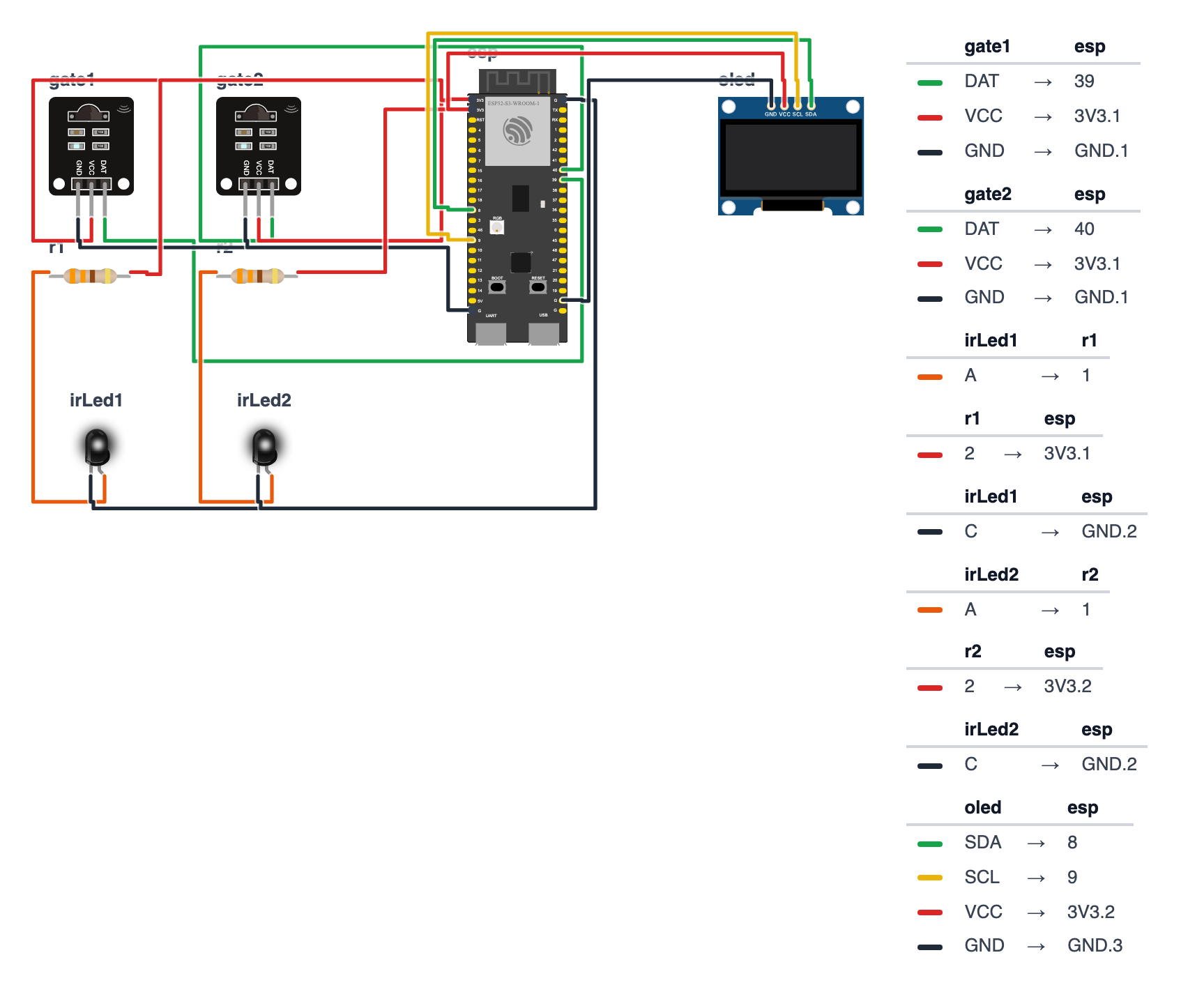
- Signal → board GPIO 39 (C6: GPIO 0) (no pullup needed)
- VCC → 3.3V
- GND → GND
Gate 2 (IR receiver output): 4. Signal → board GPIO 40 (C6: GPIO 3) 5. VCC → 3.3V 6. GND → GND
Both IR LEDs: 7. IR LED anodes (+) → 330Ω resistors → 3.3V 8. IR LED cathodes (−) → GND
OLED: 9. SDA → board GPIO 8 (C6: GPIO 6) 10. SCL → board GPIO 9 (C6: GPIO 7) 11. VCC → 3.3V 12. GND → GND
Check: With nothing in the beam, receivers should output HIGH. When beam is blocked, they should go LOW. If it’s inverted, swap logic in the code.
Step 2: Flash the code
Time: ~25 minutes
Install: Adafruit SSD1306, Adafruit GFX Library
The big picture first. This program turns the ESP32 into a precision velocity meter for projectiles:
- Two IR light gates are placed 10cm apart. When a marble breaks the first beam, a stopwatch starts. When it breaks the second beam, the stopwatch stops.
micros()measures elapsed time in millionths of a second — precise enough for objects moving at several meters per second.- Velocity = distance / time = 0.10m / [time in seconds].
- Using the launch angle you set in the code, it calculates the theoretical range using the projectile motion formula and shows it on the OLED so you can compare to where the marble actually lands.
IMPORTANT: Set launchAngleDeg to your actual measured angle before uploading. A program is like a recipe. Copy this entire recipe into Arduino IDE and upload it:
// ========== CHOOSE YOUR BOARD ==========
// Uncomment the line for YOUR board:
#define BOARD_S3    // ESP32-S3-DevKitC-1
//#define BOARD_C6  // ESP32-C6-DevKitC-1
// ========================================

#ifdef BOARD_S3
  #define PIN_SDA     8
  #define PIN_SCL     9
  #define PIN_GATE1   39
  #define PIN_GATE2   40
#endif
#ifdef BOARD_C6
  #define PIN_SDA     6
  #define PIN_SCL     7
  #define PIN_GATE1   0
  #define PIN_GATE2   3
#endif

#include <Wire.h>
#include <Adafruit_GFX.h>
#include <Adafruit_SSD1306.h>
#include <math.h>

Adafruit_SSD1306 display(128, 64, &Wire, -1);

#define GATE1_PIN PIN_GATE1
#define GATE2_PIN PIN_GATE2

const float GATE_DISTANCE = 0.100;
const float G = 9.81;
float launchAngleDeg = 35.0;

float velocity = 0;
float theoreticalRange = 0;
unsigned long t1 = 0, t2 = 0;
int trialCount = 0;
float velocities[20];
bool waitingForGate1 = true;

float calculateRange(float v0, float angleDeg) {
  float angleRad = angleDeg * PI / 180.0;
  return (v0 * v0 * sin(2 * angleRad)) / G;
}

void updateDisplay() {
  display.clearDisplay();
  display.setTextSize(1);
  display.setCursor(0, 0);
  display.println("Projectile Tracker");

  if (velocity > 0) {
    display.setCursor(0, 12);
    display.println("v0 = " + String(velocity, 3) + " m/s");

    display.setCursor(0, 22);
    display.println("Angle = " + String(launchAngleDeg, 1) + " deg");

    display.setCursor(0, 32);
    display.println("Calc Range:");
    display.setCursor(0, 42);
    display.setTextSize(2);
    display.println(String(theoreticalRange * 100, 1) + " cm");

    display.setTextSize(1);
    display.setCursor(0, 56);
    display.println("n=" + String(trialCount) + " trials");
  } else {
    display.setCursor(5, 24);
    display.println("Waiting for");
    display.setCursor(5, 36);
    display.println("projectile...");
  }

  display.display();
}

void setup() {
  Serial.begin(115200);
  Wire.begin(PIN_SDA, PIN_SCL);
  display.begin(SSD1306_SWITCHCAPVCC, 0x3C);

  pinMode(GATE1_PIN, INPUT);
  pinMode(GATE2_PIN, INPUT);

  display.clearDisplay();
  display.setTextSize(1);
  display.setCursor(5, 20);
  display.println("Set launchAngleDeg");
  display.setCursor(5, 32);
  display.println("in code first!");
  display.display();
  delay(2000);

  updateDisplay();
  Serial.println("trial,time_us,velocity_ms,calc_range_cm");
}

void loop() {
  if (waitingForGate1) {
    if (digitalRead(GATE1_PIN) == LOW) {
      t1 = micros();
      waitingForGate1 = false;

      while (digitalRead(GATE1_PIN) == LOW) delayMicroseconds(10);
    }
  } else {
    if (digitalRead(GATE2_PIN) == LOW) {
      t2 = micros();
      waitingForGate1 = true;

      unsigned long deltaT_us = t2 - t1;
      float deltaT_s = deltaT_us / 1000000.0;
      float v0 = GATE_DISTANCE / deltaT_s;

      if (v0 > 0.1 && v0 < 10.0) {
        velocity = v0;
        theoreticalRange = calculateRange(v0, launchAngleDeg);

        velocities[trialCount % 20] = v0;
        trialCount++;

        Serial.printf("%d,%lu,%.4f,%.2f\n", trialCount, deltaT_us, v0, theoreticalRange * 100);
        updateDisplay();

        while (digitalRead(GATE2_PIN) == LOW) delayMicroseconds(10);
        delay(500);
      }
    }

    if (t1 > 0 && micros() - t1 > 1000000) {
      waitingForGate1 = true;
      t1 = 0;
    }
  }
}
Line-by-line: what every line does and why
Lines 1–4: Borrowing ready-made tools
#include <Wire.h>
#include <Adafruit_GFX.h>
#include <Adafruit_SSD1306.h>
#include <math.h>
#include means “grab this instruction book.” math.h provides sin() and PI for the projectile range formula. Without it the math functions wouldn’t be available.
Lines 8–13: Gate and physics constants
#define GATE1_PIN PIN_GATE1
#define GATE2_PIN PIN_GATE2
const float GATE_DISTANCE = 0.100;
const float G = 9.81;
float launchAngleDeg = 35.0;
GATE1_PIN and GATE2_PIN are nicknames for the two gate legs: 39 and 40 (C6: 0 and 3). GATE_DISTANCE = 0.100 is 10 centimeters expressed in meters. This MUST match your actual gate spacing — measure it carefully. G = 9.81 is Earth’s gravitational acceleration in m/s². launchAngleDeg is the only thing you change for each experiment run. It is float (not const) so you can update it between trials.
Lines 15–19: Results storage
float velocity = 0;
float theoreticalRange = 0;
unsigned long t1 = 0, t2 = 0;
int trialCount = 0;
bool waitingForGate1 = true;
t1 and t2 are the timestamps when each gate was triggered. unsigned long holds very large numbers (up to about 4 billion) — needed because micros() grows quickly. bool waitingForGate1 is a simple two-state switch: true = waiting for the first gate, false = waiting for the second gate.
Lines 21–25: calculateRange() — the physics formula
float calculateRange(float v0, float angleDeg) {
  float angleRad = angleDeg * PI / 180.0;
  return (v0 * v0 * sin(2 * angleRad)) / G;
}
This function takes initial velocity v0 and angle in degrees, returns the theoretical range in meters. angleDeg * PI / 180.0 converts degrees to radians — because sin() in code always uses radians, not degrees. One radian = about 57.3°. v0 * v0 is v₀², sin(2 * angleRad) is sin(2θ). The full expression v₀²sin(2θ)/g is the standard projectile range formula from physics class.
Lines 27–54: updateDisplay() — two different screens
if (velocity > 0) {
  display.println("v0 = " + String(velocity, 3) + " m/s");
  ...
  display.println(String(theoreticalRange * 100, 1) + " cm");
} else {
  display.println("Waiting for projectile...");
}
Before any projectile triggers the gates, velocity = 0 and the screen shows “Waiting.” After the first successful measurement, velocity > 0 and the screen switches to showing results. theoreticalRange * 100 converts meters to centimeters for easier comparison to your ruler measurement.
Lines 56–71: setup() — morning routine
pinMode(GATE1_PIN, INPUT);
pinMode(GATE2_PIN, INPUT);
Both gate pins are set as inputs — the ESP32 listens to them. No INPUT_PULLUP here because the IR receiver modules have their own internal pull-up resistors and output 3.3V by themselves (HIGH when beam is clear, LOW when beam is broken).
Lines 73–110: loop() — the two-state gate detection
The entire loop is a two-state machine:
State 1 (waitingForGate1 = true):
if (digitalRead(GATE1_PIN) == LOW) {
  t1 = micros();
  waitingForGate1 = false;
  while (digitalRead(GATE1_PIN) == LOW) delayMicroseconds(10);
}
When Gate 1 goes LOW (beam broken), record the exact microsecond in t1, flip to state 2. The while loop waits for the beam to clear again (the marble passes through).
State 2 (waitingForGate1 = false):
if (digitalRead(GATE2_PIN) == LOW) {
  t2 = micros();
  unsigned long deltaT_us = t2 - t1;
  float deltaT_s = deltaT_us / 1000000.0;
  float v0 = GATE_DISTANCE / deltaT_s;
Gate 2 triggers: record t2. deltaT_us = t2 - t1 is the time between gates in microseconds. Dividing by one million converts to seconds. v0 = GATE_DISTANCE / deltaT_s is the fundamental physics: velocity = distance ÷ time.
if (v0 > 0.1 && v0 < 10.0) {This filter rejects readings that are obviously wrong — slower than 0.1 m/s (probably a noise glitch) or faster than 10 m/s (physically impossible for a hand-rolled marble).
if (t1 > 0 && micros() - t1 > 1000000) {
  waitingForGate1 = true;
  t1 = 0;
}
Timeout: if Gate 2 hasn’t triggered within 1 second after Gate 1, something went wrong (marble missed Gate 2). Reset to state 1 and try again.
The whole thing in one sentence
The device waits for a marble to break Gate 1, starts a microsecond timer, then waits for it to break Gate 2 to stop the timer — from the 10cm distance and the elapsed time it calculates velocity and the predicted landing distance.
First thing to try: wave your finger through Gate 1, then Gate 2 about 0.1 seconds later. The display should show a very low velocity (maybe 1 m/s) and a short predicted range. This confirms both gates are working before you set up the ramp.
IMPORTANT: Set
launchAngleDegto your actual protractor-measured launch angle before uploading.
Step 3: Measure precisely
Setting up the ramp:
- Build or use a ramp at your chosen angle
- Position the two gates right at the bottom where the ball goes airborne
- Measure the exact distance between gates (center-to-center of beam) in meters
- Update
GATE_DISTANCEin code - Measure launch angle with a protractor and update
launchAngleDeg
Running trials:
- Place a piece of carbon paper or chalk paper at the expected landing zone
- Roll the marble down the ramp
- Watch the OLED for v₀ and calculated range
- Measure actual landing distance with a tape measure
- Record: v₀, calculated range, actual range, percent error
Run 5–10 trials at each of 3 different launch angles.
Presentation tip: Set up the ramp live. Roll the marble. Show the OLED reading immediately: “The gates measured 2.84 m/s. My formula predicts it should land 73 cm away. [Roll it] — it landed at 71 cm. 2.7% error. The remaining error comes from air resistance, which my model doesn’t account for — the actual range is slightly shorter, as expected.”
What just happened
You built a precision timing instrument using hardware interrupts (or polling at microsecond resolution). The ESP32 measures elapsed time between two events with 1μs resolution. At 3 m/s over 10cm, the transit time is about 33ms — well within micros() precision.
The projectile motion equations are Newton’s kinematic equations:
- Horizontal: x = v₀cos(θ)t
- Vertical: y = v₀sin(θ)t - ½gt²
At maximum range (y=0): t = 2v₀sin(θ)/g, giving Range = v₀²sin(2θ)/g.
Curriculum connections:
- AP Physics 1: Kinematics, projectile motion, experimental design
- AP Physics C: Calculus-based kinematics, vectors
- NGSS HS-PS2-1: Analyze data to support Newton’s Second Law
Real ballistics labs (military, aerospace) use exactly these measurements. Your two-gate timing system is identical in principle to the ballistic chronographs used to measure bullet velocities.
Level Up
Air resistance quantification: Compare measured range vs. calculated range. The difference is due to air resistance. At what velocity does the discrepancy become significant? Fit a drag coefficient.
Angle optimization: Measure range at 10°, 20°, 30°, 45°, 60°, 70°, 80°. Plot range vs. angle. Maximum range should occur at 45° (in vacuum). Does air resistance shift the optimal angle?
Energy analysis: Use the INA219 sensor to measure the potential energy at the top of the ramp (mass × g × height). Compare to kinetic energy (½mv²) measured by the gates. What percentage is lost to friction?
Troubleshooting
| Problem | Fix |
|---|---|
| Gates never trigger | Check that the IR LED is illuminating the receiver. Use phone camera to see IR glow. Check alignment. |
| Both gates trigger simultaneously | Projectile is hitting both gates at once — increase separation, or check software timing. |
| Velocity reads very wrong | Check GATE_DISTANCE is accurate (in meters). 10cm = 0.100m. |
| Triggers from ambient light | Shield the gates from strong overhead light. Cardboard cover helps. |
| Upload fails | Hold BOOT button while clicking Upload. |