Parent info
Parts you need
Affiliate links — we may earn a small commission
Try this circuit in your browser!
Run the code, press the buttons and watch what happens — before you buy any parts. No account needed.
Open in Simulator →Your classmates dropped a ruler. You measured 247ms.
Imagine this: Psychology class. Reaction time experiment. The classic method: hold a ruler vertically, partner drops it without warning, catch it, measure distance fallen, calculate time using free-fall formula.
Error sources: hesitation in the dropper, grip width variation, the equation assumes you start moving at the exact moment it drops.
Your method: a bright LED lights up at a random time. Your partner hits a button as fast as possible. The display shows: 247ms. You average 30 trials per person. You test reaction time: before coffee vs. after, morning vs. afternoon, dominant hand vs. non-dominant, distracted vs. focused.
Real data. Real psychology.
That’s what we’re building. For about $18.
What you’ll need
| Part | What it does | Price |
|---|---|---|
| ESP32-S3-DevKitC-1 | Brain — random timing, millisecond measurement, statistics | ~$12 |
| OLED display 0.96” | Shows reaction time, statistics, trial history | ~$4 |
| Push button | The response button — hit this when you see the light | ~$2 |
| LED (WS2812B single) | The stimulus — flashes when you should respond | ~$3 |
You also need: cardboard or small box to mount everything.
Total: ~$18 | Time: ~1–2 hours | Difficulty: ●●○○○
How it works (60 seconds)
The test is simple:
- Wait a random time (2–5 seconds — unpredictable so the person can’t anticipate)
- Flash the LED
- Start counting milliseconds
- The person hits the button
- Stop counting — that’s their reaction time
The ESP32’s millis() function counts milliseconds since startup with about 1ms accuracy. Human reaction time to visual stimuli averages 200–300ms — well within what millis() can measure.
Collect 10–30 trials per condition, compute mean and standard deviation, compare conditions.
Step 0: Design your psychology experiment
Time: ~20 minutes (research and planning)
A strong psychology experiment has a clear independent variable (what you change) and dependent variable (what you measure).
Hypothesis options:
| Study | Independent Variable | Prediction |
|---|---|---|
| Dominant hand | Dominant vs. non-dominant hand | Dominant hand faster |
| Time of day | Morning vs. afternoon vs. evening | Afternoon fastest |
| Distraction | Focused vs. counting backwards | Focused faster |
| Practice effect | Trial 1–10 vs. Trial 21–30 | Later trials faster |
| Caffeine | Before vs. 30 min after coffee | After faster |
| Age | 15-year-olds vs. teachers | Adults likely slower |
Controls: Same person, same light stimulus, same button, same instructions, same ambient conditions. The only thing that changes is your independent variable.
Step 1: Wire it up
Time: ~10 minutes
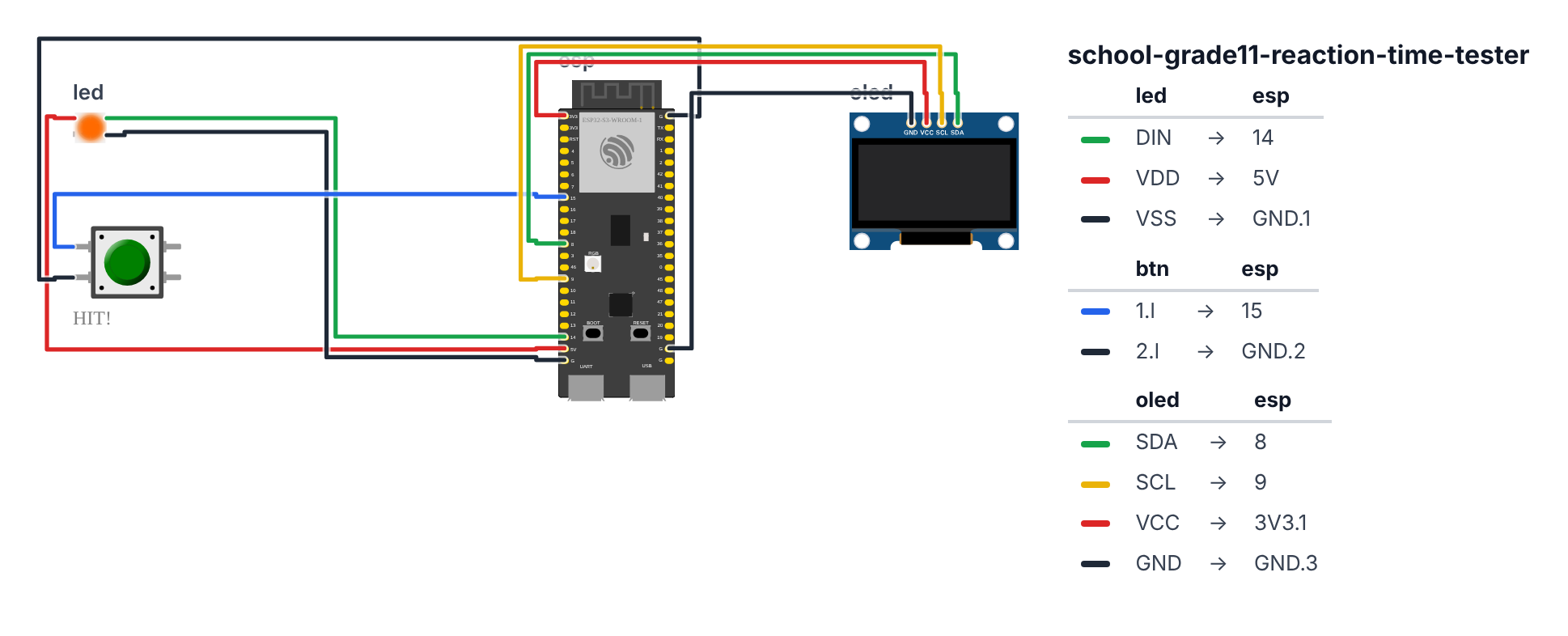
LED (single WS2812B):
- DIN → board GPIO 14 (C6: GPIO 8)
- VCC → 5V
- GND → GND
Response button: 4. One leg → board GPIO 15 (C6: GPIO 3) 5. Other leg → GND (Use INPUT_PULLUP)
OLED: 6. SDA → board GPIO 8 (C6: GPIO 6) 7. SCL → board GPIO 9 (C6: GPIO 7) 8. VCC → 3.3V 9. GND → GND
Check: Simple wiring — button, LED, display. Make sure the button leg goes to GND, not 5V.
Step 2: Flash the code
Time: ~15 minutes
Install: FastLED, Adafruit SSD1306, Adafruit GFX Library
The big picture first. This program turns the ESP32 into a psychology lab instrument:
- It uses a state machine — think of it like a traffic light that can only be in one mode at a time (WAITING → READY → DELAY → STIMULUS → result).
- A random delay (2–5 seconds) prevents the person from guessing when the light will flash.
millis()measures the exact moment the light turns on and the exact moment the button is pressed. The difference is the reaction time.- It keeps running statistics (mean, min, max, standard deviation) and prints CSV data to Serial Monitor for your spreadsheet.
A program is like a recipe. Copy this entire recipe into Arduino IDE and upload it:
// ========== CHOOSE YOUR BOARD ==========
// Uncomment the line for YOUR board:
#define BOARD_S3    // ESP32-S3-DevKitC-1
//#define BOARD_C6  // ESP32-C6-DevKitC-1
// ========================================

#ifdef BOARD_S3
  #define PIN_SDA       8
  #define PIN_SCL       9
  #define PIN_NEOPIXEL  14
  #define PIN_BUTTON    15
#endif
#ifdef BOARD_C6
  #define PIN_SDA       6
  #define PIN_SCL       7
  #define PIN_NEOPIXEL  8
  #define PIN_BUTTON    3
#endif

#include <FastLED.h>
#include <Wire.h>
#include <Adafruit_GFX.h>
#include <Adafruit_SSD1306.h>

#define LED_PIN   PIN_NEOPIXEL
#define BTN_PIN   PIN_BUTTON
#define NUM_LEDS  1

CRGB leds[1];
Adafruit_SSD1306 display(128, 64, &Wire, -1);

float reactions[100];
int trialCount = 0;
float sumRT = 0;
float minRT = 9999;
float maxRT = 0;

enum State { WAITING, READY_TO_START, WAITING_DELAY, STIMULUS_ON, TOO_EARLY };
State state = WAITING;

unsigned long stimulusTime = 0;
unsigned long delayEnd = 0;
float lastRT = 0;

float getMean() { return trialCount > 0 ? sumRT / trialCount : 0; }

float getStdDev() {
  if (trialCount < 2) return 0;
  float mean = getMean();
  float sumSq = 0;
  for (int i = 0; i < trialCount; i++) sumSq += (reactions[i] - mean) * (reactions[i] - mean);
  return sqrt(sumSq / trialCount);
}

void updateDisplay() {
  display.clearDisplay();

  switch (state) {
    case WAITING:
      display.setTextSize(1);
      display.setCursor(5, 0);
      display.println("Reaction Time Test");
      display.setCursor(5, 20);
      display.println("Press button to start");
      if (trialCount > 0) {
        display.setCursor(0, 40);
        display.println("Last: " + String(lastRT, 0) + "ms");
        display.setCursor(0, 52);
        display.println("Avg: " + String(getMean(), 0) + "ms n=" + String(trialCount));
      }
      break;

    case READY_TO_START:
      display.setTextSize(1);
      display.setCursor(10, 20);
      display.println("Get ready...");
      display.setCursor(10, 36);
      display.println("Watch the LED!");
      break;

    case WAITING_DELAY:
      display.setTextSize(1);
      display.setCursor(20, 28);
      display.println("...");
      break;

    case STIMULUS_ON:
      display.setTextSize(1);
      display.setCursor(25, 20);
      display.println("HIT IT NOW!");
      display.setTextSize(2);
      display.setCursor(15, 36);
      display.println("PRESS!");
      break;

    case TOO_EARLY:
      display.setTextSize(1);
      display.setCursor(15, 20);
      display.println("Too early!");
      display.setCursor(10, 36);
      display.println("Wait for the light.");
      display.setCursor(10, 50);
      display.println("Press to try again.");
      break;
  }

  display.display();
}

void showResults() {
  display.clearDisplay();
  display.setTextSize(1);
  display.setCursor(0, 0);
  display.println("=== RESULTS ===");
  display.setCursor(0, 12);
  display.println("Trials: " + String(trialCount));
  display.setCursor(0, 22);
  display.println("Mean: " + String(getMean(), 1) + " ms");
  display.setCursor(0, 32);
  display.println("Min:  " + String(minRT, 1) + " ms");
  display.setCursor(0, 42);
  display.println("Max:  " + String(maxRT, 1) + " ms");
  display.setCursor(0, 52);
  display.println("StdDev: " + String(getStdDev(), 1) + " ms");
  display.display();
  delay(3000);
}

void setup() {
  Serial.begin(115200);
  FastLED.addLeds<WS2812B, LED_PIN, GRB>(leds, NUM_LEDS);
  FastLED.setBrightness(100);
  leds[0] = CRGB::Black;
  FastLED.show();

  Wire.begin(PIN_SDA, PIN_SCL);
  display.begin(SSD1306_SWITCHCAPVCC, 0x3C);
  pinMode(BTN_PIN, INPUT_PULLUP);

  randomSeed(esp_random());

  Serial.println("trial,reaction_ms");
  updateDisplay();
}

void loop() {
  bool btnPressed = (digitalRead(BTN_PIN) == LOW);

  switch (state) {
    case WAITING:
      leds[0] = CRGB::Black;
      FastLED.show();
      if (btnPressed) {
        delay(200);
        state = READY_TO_START;
        updateDisplay();
        delay(1000);
        delayEnd = millis() + random(2000, 5000);
        state = WAITING_DELAY;
        updateDisplay();
      }
      break;

    case WAITING_DELAY:
      leds[0] = CRGB::Black;
      FastLED.show();
      if (btnPressed) {
        state = TOO_EARLY;
        updateDisplay();
      }
      if (millis() >= delayEnd) {
        leds[0] = CRGB::Green;
        FastLED.show();
        stimulusTime = millis();
        state = STIMULUS_ON;
        updateDisplay();
      }
      break;

    case STIMULUS_ON:
      if (btnPressed) {
        unsigned long rt = millis() - stimulusTime;
        lastRT = rt;

        if (trialCount < 100) {
          reactions[trialCount++] = rt;
          sumRT += rt;
          if (rt < minRT) minRT = rt;
          if (rt > maxRT) maxRT = rt;
        }

        Serial.println(String(trialCount) + "," + String(rt));

        leds[0] = CRGB::Blue;
        FastLED.show();
        delay(300);
        leds[0] = CRGB::Black;
        FastLED.show();

        if (trialCount % 10 == 0 && trialCount > 0) {
          showResults();
        }

        state = WAITING;
        updateDisplay();
      }
      if (millis() - stimulusTime > 2000) {
        leds[0] = CRGB::Red;
        FastLED.show();
        delay(500);
        state = WAITING;
        updateDisplay();
      }
      break;

    case TOO_EARLY:
      leds[0] = CRGB::Red;
      FastLED.show();
      if (btnPressed) {
        delay(200);
        state = WAITING;
        leds[0] = CRGB::Black;
        FastLED.show();
        updateDisplay();
      }
      break;

    case READY_TO_START:
      break;
  }
}
Line-by-line: what every line does and why
Lines 1–4: Borrowing ready-made tools
#include <FastLED.h>
#include <Wire.h>
#include <Adafruit_GFX.h>
#include <Adafruit_SSD1306.h>
#include means “grab this instruction book.” FastLED is the book for controlling the WS2812B color LED. The other three handle I2C wiring, graphics drawing, and the OLED display.
Lines 6–8: Pin names
#define LED_PIN   PIN_NEOPIXEL
#define BTN_PIN   PIN_BUTTON
#define NUM_LEDS  1
#define gives numbers nicknames. LED is on pin 14 (C6: pin 8), the button is on pin 15 (C6: pin 3), and we have 1 LED total. Using names instead of numbers makes the code easier to read and change.
Lines 10–11: The LED array
CRGB leds[1];CRGB is a type that holds a color (Red, Green, Blue). leds[1] is a one-slot shelf for the single LED. To set it green: leds[0] = CRGB::Green. To turn it off: leds[0] = CRGB::Black.
Lines 13–17: Statistics storage
float reactions[100];
int trialCount = 0;
float sumRT = 0;
float minRT = 9999;
float maxRT = 0;
reactions[100] is a shelf with 100 slots for storing reaction times. sumRT keeps a running total so we can calculate the mean. minRT starts at 9999 — every real reaction time will be smaller, so it gets replaced immediately on the first trial. maxRT starts at 0 — every real reaction time will be larger.
Lines 19–20: The state machine
enum State { WAITING, READY_TO_START, WAITING_DELAY, STIMULUS_ON, TOO_EARLY };
State state = WAITING;
enum defines a list of named choices — like a traffic light that can only show one color at a time. State is the type, and state is the current mode. Starting in WAITING means the device sits idle until someone presses the button.
Lines 22–24: Timing variables
unsigned long stimulusTime = 0;
unsigned long delayEnd = 0;
float lastRT = 0;
stimulusTime records the exact millisecond the LED flashes. delayEnd records when the random waiting period expires and the LED should flash. unsigned long is a type that holds large whole numbers — millis() can reach very large values after hours of running, and unsigned long handles that without overflowing.
Lines 26–34: getMean() and getStdDev() — statistics functions
float getMean() { return trialCount > 0 ? sumRT / trialCount : 0; }This is a one-line function. The ? and : form a shorthand if/else: “if trialCount is greater than 0, return the sum divided by the count; otherwise return 0.” Dividing the total sum by the number of trials gives the average (mean).
float getStdDev() {
  ...
  for (int i = 0; i < trialCount; i++) sumSq += (reactions[i] - mean) * (reactions[i] - mean);
  return sqrt(sumSq / trialCount);
}
Standard deviation measures how spread out the data is. For each reaction time, it calculates how far it is from the mean, squares that distance, and adds them all up. Then sqrt(sumSq / trialCount) gives the standard deviation. A small SD means consistent reactions. A large SD means variable.
Lines 36–72: updateDisplay() — the screen for each state
switch (state) {
  case WAITING: ... break;
  case STIMULUS_ON: ... break;
  case TOO_EARLY: ... break;
}
switch is like a multi-door hallway — it jumps to the correct “case” based on the current state. Each break exits the switch. This is how the same function draws completely different screens depending on what mode the device is in.
Lines 74–89: showResults() — the summary screen
Every 10 trials, this function clears the screen and writes all statistics. After 3 seconds (delay(3000)) the main loop continues automatically.
Lines 91–102: setup() — the morning routine
FastLED.addLeds<WS2812B, LED_PIN, GRB>(leds, NUM_LEDS);
FastLED.setBrightness(100);
leds[0] = CRGB::Black;
FastLED.show();
addLeds registers the LED strip (type WS2812B, on LED_PIN, using GRB color order). Brightness 100 out of 255. Setting to Black and calling FastLED.show() ensures the LED starts off — no leftover color from a previous run.
randomSeed(esp_random());random() generates numbers that look random but are actually a predictable sequence. randomSeed() picks a starting point for that sequence. esp_random() returns a number from the ESP32’s hardware random number generator, which uses radio noise — essentially random. This makes the delays genuinely unpredictable each time.
Lines 104–160: loop() — the state machine in action
bool btnPressed = (digitalRead(BTN_PIN) == LOW);Every loop iteration, first check the button. digitalRead returns HIGH (not pressed, because of INPUT_PULLUP) or LOW (pressed, button connects pin to ground). == is a comparison: “is it equal to LOW?” The result is stored as bool btnPressed — true or false.
The switch (state) block then decides what to do based on both the current state and whether the button is pressed.
In WAITING_DELAY, the critical moment:
if (millis() >= delayEnd) {
  leds[0] = CRGB::Green;
  FastLED.show();
  stimulusTime = millis();
  state = STIMULUS_ON;
}
When the clock reaches delayEnd, the LED goes green, and stimulusTime records that exact millisecond. Then in STIMULUS_ON:
unsigned long rt = millis() - stimulusTime;The reaction time is simply “now minus when the light turned on.” This is the measurement.
The whole thing in one sentence
The device waits idle, then when a button press starts a trial, it waits a random 2–5 seconds, flashes the LED green, and measures exactly how many milliseconds pass before the button is pressed — counting it invalid if the button was pressed too early.
First thing to try: run 10 trials yourself, then run 10 trials while counting backwards from 100 out loud. Compare the two means. Distraction should make your average slower — that’s your experiment.
Check: Press the button once. The display should say “Get ready…” then show a random delay, then the LED goes green. Hit the button — OLED shows your reaction time. If the LED flashes immediately on startup, there’s a wiring issue with the button.
Step 3: Run your study
Protocol (for valid data):
- Explain the task clearly: “Press the button as fast as you can when the light turns green. Don’t press before it lights up — that’s too early and doesn’t count.”
- Practice trials: 3–5 practice trials before recording
- Recording trials: 10–20 trials per condition
- Rest between conditions: 2+ minutes rest to prevent fatigue
- Blind the participants: Don’t tell them which “condition” they’re in if you’re testing something like “distraction”
Export data: Copy from Serial Monitor — it outputs trial,reaction_ms CSV format. Paste into Google Sheets. Calculate mean, standard deviation, run a t-test if you’ve learned statistics.
Presentation tip: Run the device live. Volunteer from the audience tries it. Show their result. Then say: “The average across 20 trials for my subjects was [X] ms. Research literature shows average visual reaction time is 200–250ms. Ours [match/differ] because [your explanation]. The fastest response in our data was [X]ms — that’s about the minimum possible given neural transmission time from eye to hand, roughly 150ms.”
What just happened
You built a reaction time measurement apparatus — the same type used in psychology research labs. The key innovation over the ruler test: random delay prevents anticipation. If the delay were fixed at 3 seconds, subjects could just press at 3 seconds without reacting to the light at all. Random delays require genuine reaction.
millis() on the ESP32 counts in units of 1ms. The CPU clock runs at 240MHz — fast enough that the millis() timer is far more precise than human reaction time.
Curriculum connections:
- AP Psychology: Research methods, experimental design, statistics
- NGSS Science Practice 3: Planning and carrying out investigations
- Common Core Math S-ID: Summarizing, representing, and interpreting data on two variables
The standard deviation tells you about individual consistency — low SD = reliable fast responder, high SD = variable (perhaps distracted). This is an actual measurement psychologists use.
Level Up
Auditory vs. visual: Add a buzzer. Compare reaction times to a sound stimulus vs. a light stimulus. Research shows auditory reaction time (~150ms) is faster than visual (~250ms) — test whether your data confirms this.
N-back test: Instead of always reacting to green, only react when the light was green the LAST time. This tests working memory, not just reaction time.
Motor learning: Give 100 consecutive trials without breaks. Plot trial number vs. reaction time. You should see improvement (learning curve) then leveling off.
Troubleshooting
| Problem | Fix |
|---|---|
| “Too early” triggers without pressing | Button is noisy — add delay(50) after detecting press, then re-read button to confirm. |
| LED doesn’t light | Check GPIO 14 (C6: GPIO 8), 5V power, DIN not DOUT. |
| Very fast reads (<100ms) | Possible button bounce triggering immediately after stimulus. |
| Results not saving | Check the CSV in Serial Monitor. Copy before resetting. |
| Upload fails | Hold BOOT button while clicking Upload. |