Parent info
Parts you need
Affiliate links — we may earn a small commission
Try this circuit in your browser!
Run the code, press the buttons and watch what happens — before you buy any parts. No account needed.
Open in Simulator →Your fish will never experience a surprise cold snap again.
Imagine this: it’s 2am. Your aquarium heater quietly fails. By morning, your tropical fish are stressed or worse — and you had no idea. Now imagine your phone buzzing at 2am with a Telegram message: “Tank temperature dropped below 22°C — heater may have failed.” You wake up, check the dashboard, and handle it.
That’s what this controller does. It monitors water temperature every 5 seconds, controls the heater via a relay, and gives your fish a beautiful automatic sunrise at 8am and sunset at 8pm — every single day, without you touching anything.
Build time: 2.5 hours. Cost: ~$29.
What you’ll need
| Part | What it does | Price |
|---|---|---|
| ESP32-S3 Dev Board | The brain. Reads temperature, controls relay and LEDs, serves dashboard. | ~$12 |
| DS18B20 Waterproof Probe | Stainless steel tip safe in water. Reads temperature to ±0.5°C accuracy. | ~$4 |
| 5V Relay Module | Switches the aquarium heater on and off. ESP32 sends a signal, relay handles the mains. | ~$3 |
| WS2812B LED Strip 1m | Full-color addressable LEDs for sunrise/sunset effects. Get the waterproof version. | ~$10 |
| 4.7kΩ resistor | Required by the DS18B20 — it can’t read correctly without this pull-up. | ~$0.10 |
You also need: home WiFi, the free Arduino IDE, and a USB power supply (or the tank hood’s existing 5V USB port).
Total: ~$29 | Time: ~2.5 hours | Difficulty: ●●●○○
ELECTRICITY + WATER SAFETY — read this before building: The ESP32 side runs at 5V and is completely safe. The relay’s HIGH-VOLTAGE SIDE connects to your aquarium heater (mains voltage, 110V or 230V). These two sides of the relay MUST be kept separate. Use a proper terminal block for mains connections. Never use bare wire ends. Never work on the mains side while the heater is plugged in. If you are under 16, ask an adult to make the relay-to-heater connection.
How it works (60 seconds)
Think of it like a car’s cruise control, but for water temperature. You set a target range (say, 24–26.5°C). When the water drops below 24°C, the ESP32 closes the relay — this completes the heater’s electrical circuit and turns it on. When the water rises above 26.5°C, the relay opens and the heater turns off.
The gap between the on-threshold and the off-threshold (the “dead band”) is critical — without it, the relay would switch thousands of times per second at exactly 25°C, burning itself out in days.
The LED strip uses real time from the internet (NTP) to run a lighting schedule. At 8am it gradually shifts from deep orange to warm white over 30 minutes — a sunrise your fish actually benefit from. At 8pm, a slow sunset fades to off.
Step 0: Plan your tank layout
Time: ~5 minutes
Decide where things will mount:
- DS18B20 probe: In the water, away from the heater output. Use a suction cup clip from any aquarium store.
- Relay module: Outside the tank in a dry spot. A small project box is ideal.
- LED strip: Along the inside rim of the tank hood, or across the top. WS2812B strips have adhesive backing.
- ESP32 board: Outside the tank, near the relay. USB-powered.
Keep the relay module completely dry. Seal any cable entry points with aquarium-safe silicone if needed.
Step 1: Wire it up
Time: ~20 minutes
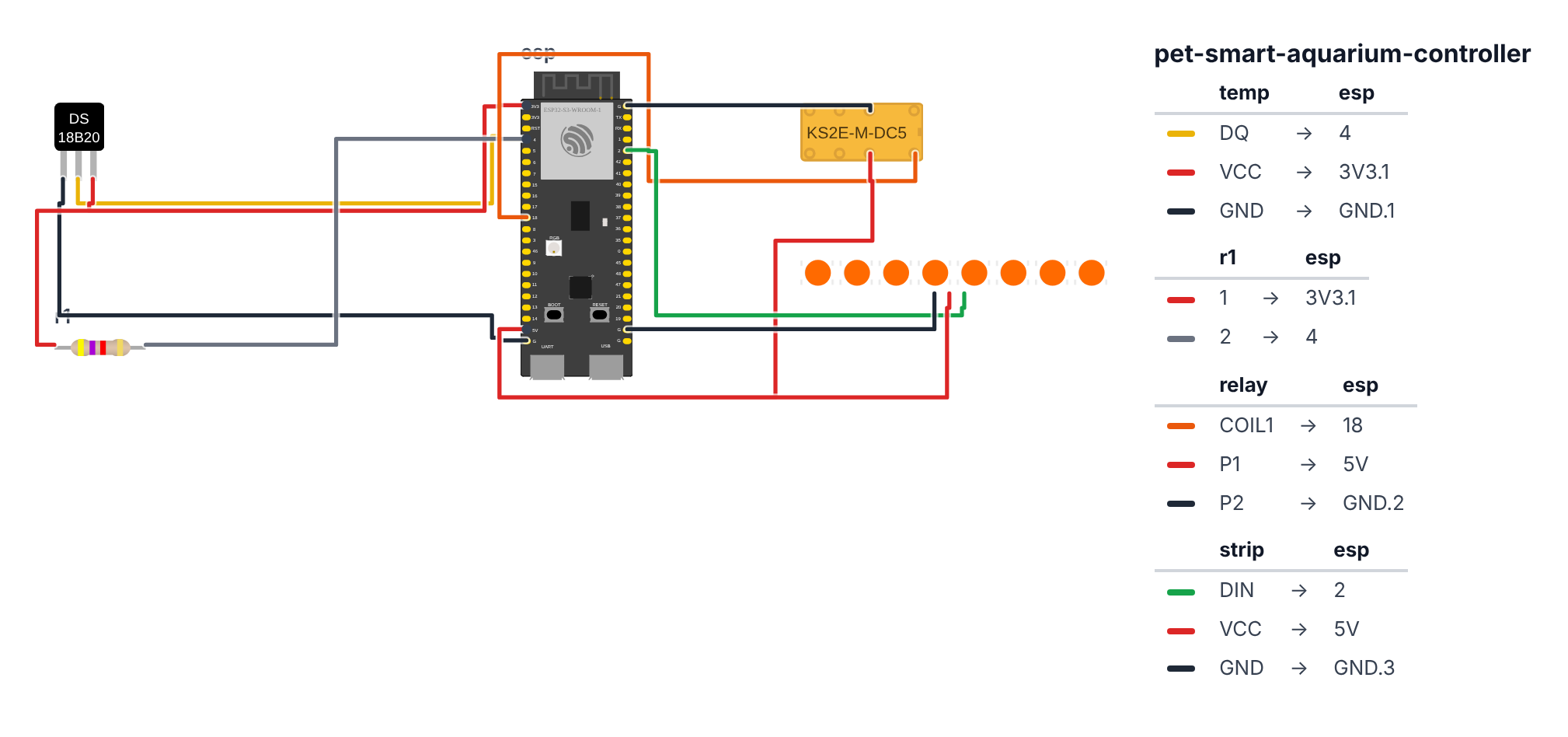
DS18B20 Temperature Probe (3 wires + 1 resistor):
- DS18B20 Data (yellow wire) → ESP32 GPIO 4 (C6: GPIO 0)
- DS18B20 VCC (red wire) → ESP32 3.3V
- DS18B20 GND (black wire) → ESP32 GND
- 4.7kΩ resistor between DS18B20 Data and 3.3V (connects the yellow wire to 3.3V — required for the sensor to work)
Relay Module: 5. Relay IN → ESP32 GPIO 18 (C6: GPIO 11) — orange wire 6. Relay VCC → ESP32 VIN (5V) — red wire 7. Relay GND → ESP32 GND — black wire
WS2812B LED Strip: 8. Strip Data In → ESP32 GPIO 2 (C6: GPIO 8) — green wire 9. Strip VCC → ESP32 VIN (5V) — red wire (use a separate 5V supply for strips with more than 30 LEDs) 10. Strip GND → ESP32 GND — black wire
Heater connection to relay (ask an adult if under 16):
- Relay COM → one wire of the heater’s power cable
- Relay NO (Normally Open) → the mains power supply to the heater
- The other heater wire goes straight to the mains socket
Check: DS18B20 has 3 wires. Most waterproof versions: yellow = data, red = VCC, black = GND. Verify with your specific probe datasheet. The pull-up resistor is not optional.
Check: The relay board has two sides. The low-voltage side (IN, VCC, GND) connects to the ESP32. The high-voltage side (COM, NO, NC) connects to the heater. Keep these physically separated with no bare wire crossings.
Step 2: Upload the code
Time: ~15 minutes
Install these libraries in Arduino IDE (Sketch > Manage Libraries):
OneWireby Paul StoffregenDallasTemperatureby Miles BurtonFastLEDby Daniel GarciaESPAsyncWebServerby Me-No-Dev
The big picture first. This program does three things automatically, forever.
- Temperature control: every 5 seconds it reads the water temperature. If it drops below 24°C, the relay closes and the heater turns on. If it rises above 26.5°C, the relay opens and the heater turns off. The 2.5°C gap between those numbers is called a “dead band” — it prevents the relay from switching constantly right at the edge, which would burn it out.
- Lighting schedule: using time from the internet, the LED strip wakes up at 8am with a slow warm orange sunrise, runs at warm white all day, and fades out with a sunset at 8pm. Your fish benefit from a consistent light cycle.
- Web dashboard: a temperature history chart is always available at the ESP32’s IP address. Open it to see the last hour of water temperature as a line graph.
// ========== CHOOSE YOUR BOARD ==========
// Uncomment the line for YOUR board:
#define BOARD_S3    // ESP32-S3-DevKitC-1
//#define BOARD_C6  // ESP32-C6-DevKitC-1
// ========================================

#ifdef BOARD_S3
  #define PIN_TEMP             4
  #define PIN_RELAY            18
  #define PIN_NEOPIXEL         2
#endif
#ifdef BOARD_C6
  #define PIN_TEMP             0
  #define PIN_RELAY            11
  #define PIN_NEOPIXEL         8
#endif

#include <OneWire.h>
#include <DallasTemperature.h>
#include <FastLED.h>
#include <WiFi.h>
#include <ESPAsyncWebServer.h>
#include <SPIFFS.h>
#include <time.h>

const char* ssid      = "YourWiFiName";
const char* password  = "YourWiFiPassword";

const int NUM_LEDS    = 60;

const float TEMP_MIN  = 24.0;
const float TEMP_MAX  = 26.5;

OneWire oneWire(PIN_TEMP);
DallasTemperature sensors(&oneWire);

CRGB leds[NUM_LEDS];
AsyncWebServer server(80);

float currentTemp   = 0;
unsigned long lastTempRead = 0;
unsigned long lastTempLog  = 0;

void updateLights() {
  struct tm t;
  getLocalTime(&t);
  int minuteOfDay = t.tm_hour * 60 + t.tm_min;

  int sunriseStart = 8  * 60;
  int sunsetStart  = 20 * 60;
  int offTime      = 22 * 60;

  if (minuteOfDay < sunriseStart || minuteOfDay >= offTime) {
    FastLED.clear();
    FastLED.show();
    return;
  }

  if (minuteOfDay >= sunriseStart && minuteOfDay < sunriseStart + 30) {
    uint8_t progress = map(minuteOfDay - sunriseStart, 0, 30, 0, 255);
    for (int i = 0; i < NUM_LEDS; i++)
      leds[i] = CHSV(map(progress, 0, 255, 10, 30), 255 - progress / 2, progress);
  } else if (minuteOfDay >= sunsetStart && minuteOfDay < offTime) {
    uint8_t progress = map(minuteOfDay - sunsetStart, 0, offTime - sunsetStart, 255, 0);
    for (int i = 0; i < NUM_LEDS; i++)
      leds[i] = CRGB(progress, (uint8_t)(progress * 0.8), (uint8_t)(progress * 0.5));
  } else {
    for (int i = 0; i < NUM_LEDS; i++) leds[i] = CRGB(255, 220, 160);
  }
  FastLED.show();
}

void setup() {
  Serial.begin(115200);
  SPIFFS.begin(true);
  sensors.begin();

  FastLED.addLeds<WS2812B, PIN_NEOPIXEL, GRB>(leds, NUM_LEDS);
  FastLED.setBrightness(180);

  pinMode(PIN_RELAY, OUTPUT);
  digitalWrite(PIN_RELAY, LOW);

  WiFi.begin(ssid, password);
  while (WiFi.status() != WL_CONNECTED) delay(500);
  configTime(0, 0, "pool.ntp.org");
  Serial.println("Aquarium controller at: " + WiFi.localIP().toString());

  server.on("/", HTTP_GET, [](AsyncWebServerRequest *req){
    File f = SPIFFS.open("/temp.csv", FILE_READ);
    String data = "";
    while (f.available()) data += (char)f.read();
    f.close();

    req->send(200, "text/html",
      "<!DOCTYPE html><html><head>"
      "<script src='https://cdn.jsdelivr.net/npm/chart.js'></script></head>"
      "<body style='background:#0a2540;color:#eee;font-family:Arial;padding:20px'>"
      "<h1 style='color:#00d4ff'>Aquarium Controller</h1>"
      "<p>Temperature: <b style='color:#00ff88'>" + String(currentTemp, 1) + " C</b></p>"
      "<p>Heater: <b>" + String(digitalRead(PIN_RELAY) ? "ON" : "OFF") + "</b></p>"
      "<canvas id='chart' width='800' height='300'></canvas>"
      "<script>"
      "const rows=`" + data + "`.trim().split('\\n');"
      "const labels=[],temps=[];"
      "rows.slice(-60).forEach(r=>{const p=r.split(',');labels.push(p[0]);temps.push(parseFloat(p[1]));});"
      "new Chart(document.getElementById('chart'),{type:'line',"
      "data:{labels,datasets:[{label:'Temperature (C)',data:temps,borderColor:'#00d4ff',fill:false}]},"
      "options:{scales:{y:{min:" + String(TEMP_MIN - 1) + ",max:" + String(TEMP_MAX + 1) + "}}}});"
      "</script></body></html>");
  });

  server.begin();
}

void loop() {
  unsigned long now = millis();

  if (now - lastTempRead > 5000) {
    lastTempRead = now;
    sensors.requestTemperatures();
    currentTemp = sensors.getTempCByIndex(0);

    if (currentTemp < TEMP_MIN) digitalWrite(PIN_RELAY, HIGH);
    if (currentTemp > TEMP_MAX) digitalWrite(PIN_RELAY, LOW);

    Serial.println("Temp: " + String(currentTemp) + "C | Heater: " +
                   String(digitalRead(PIN_RELAY) ? "ON" : "OFF"));
  }

  if (now - lastTempLog > 60000) {
    lastTempLog = now;
    struct tm t;
    getLocalTime(&t);
    String timestamp = String(t.tm_hour) + ":" + (t.tm_min < 10 ? "0" : "") + String(t.tm_min);
    File f = SPIFFS.open("/temp.csv", FILE_APPEND);
    if (f) { f.println(timestamp + "," + String(currentTemp, 1)); f.close(); }
  }

  updateLights();
  delay(1000);
}
Line-by-line: what every line does and why
Lines 1–7: Four instruction books
#include <OneWire.h>
#include <DallasTemperature.h>
#include <FastLED.h>
#include <time.h>
OneWire handles a special communication protocol where one wire carries data in both directions — like a walkie-talkie on a single wire. DallasTemperature is the instruction book specifically for the DS18B20 sensor, built on top of OneWire. FastLED controls the addressable LED strip. time.h handles internet time for the lighting schedule.
Lines 16–17: The dead band
const float TEMP_MIN  = 24.0;
const float TEMP_MAX  = 26.5;
These two numbers create a 2.5°C gap — the “dead band.” The heater turns ON below 24°C and turns OFF above 26.5°C. If both thresholds were the same number (say 25°C), the relay would click ON and OFF thousands of times per second whenever the temperature hovered at exactly 25°C. Mechanical relays fail after about 100,000 switches. The dead band means it switches only a few times per day.
Lines 19–20: Setting up the temperature sensor
OneWire oneWire(PIN_TEMP);
DallasTemperature sensors(&oneWire);
OneWire oneWire(PIN_TEMP) creates the communication channel on GPIO 4 (C6: GPIO 0). DallasTemperature sensors(&oneWire) wraps that channel with the DS18B20 instruction book. The & means “hand a reference to the oneWire object” — like handing someone a phone number so they can call it.
Line 22: The LED color buffer
CRGB leds[NUM_LEDS];CRGB is a color type — it holds red, green, and blue values (0–255 each). leds[60] is an array of 60 colors, one per LED. Changing leds[5] = CRGB(255, 0, 0) only changes the buffer in memory — it does NOT light the LED yet. Only FastLED.show() sends the buffer to the physical strip. This is a crucial pattern: build the whole frame in memory, then commit it all at once.
updateLights(): the sunrise/sunset engine
int minuteOfDay = t.tm_hour * 60 + t.tm_min;Convert hours and minutes to a single number. 8:30am = 8×60+30 = 510. This makes time comparisons simple — checking if minuteOfDay >= 480 && minuteOfDay < 510 is much cleaner than checking hours and minutes separately.
uint8_t progress = map(minuteOfDay - sunriseStart, 0, 30, 0, 255);
for (int i = 0; i < NUM_LEDS; i++)
  leds[i] = CHSV(map(progress, 0, 255, 10, 30), 255 - progress / 2, progress);
map(minuteOfDay - sunriseStart, 0, 30, 0, 255) converts “minutes into sunrise” (0–30) into a 0–255 progress value. CHSV is a color defined by Hue (color angle), Saturation, and Value (brightness). As progress rises from 0 to 255, hue shifts from 10 (deep orange) to 30 (warm yellow), saturation decreases (less vivid), and brightness increases. This produces a realistic 30-minute sunrise transition.
FastLED.show();The single most important line in the lighting code. It serializes the entire leds[] array and sends it to the physical strip in one burst. Without this, all your color changes exist only in memory — the LEDs see nothing.
loop(): the heartbeat
sensors.requestTemperatures();
currentTemp = sensors.getTempCByIndex(0);
requestTemperatures() tells the DS18B20 to take a measurement — it takes about 750ms internally. getTempCByIndex(0) fetches the result from the first sensor on the OneWire bus. If you add a second probe to the same wire, getTempCByIndex(1) gets its reading — no extra wiring needed.
if (currentTemp < TEMP_MIN) digitalWrite(PIN_RELAY, HIGH);
if (currentTemp > TEMP_MAX) digitalWrite(PIN_RELAY, LOW);
Two separate if statements — not an if/else. Between TEMP_MIN and TEMP_MAX, neither condition is true, so neither line runs. The relay stays exactly as it was — that’s the dead band in action. HIGH closes the relay (heater on). LOW opens it (heater off).
The whole thing in one sentence
The controller reads tank temperature every 5 seconds and controls the heater to stay in the target range, updates the LED strip every second to match the current time of day, and logs temperature to flash memory for the web dashboard.
First thing to try: after uploading, open Serial Monitor. You should see temperature readings every 5 seconds and “Heater: ON” or “Heater: OFF.” Check the reading — 85°C means the pull-up resistor is missing, -127°C means the probe isn’t connected.
Check: Open Serial Monitor at 115200. After WiFi connects, you should see temperature readings every 5 seconds and “Heater: ON” or “Heater: OFF”. Open the dashboard in a browser — you should see current temperature and heater status.
Step 3: Configure your fish species’ temperature range
Time: ~2 minutes
In the code, find these two lines and set them to your fish species’ ideal range:
const float TEMP_MIN  = 24.0;
const float TEMP_MAX  = 26.5;
Species reference:
- Tropical fish (neons, tetras, guppies, bettas): 24.0 / 26.5°C
- Goldfish, koi: 18.0 / 22.0°C
- Cichlids: 25.0 / 28.0°C
- Discus: 27.0 / 30.0°C
Also set the timezone in configTime(0, 0, "pool.ntp.org"). The first 0 is your UTC offset in seconds (UTC+1 = 3600, UTC-5 = -18000).
Check: After re-uploading with your settings, confirm the serial output shows reasonable temperature readings. A reading of 85°C means the pull-up resistor is missing. -127°C means the probe isn’t connected.
Step 4: Watch the sunrise!
The controller runs everything automatically now. The next morning at 8am (or your set sunrise time), the LED strip will gradually shift from deep orange to warm white over 30 minutes. Come back in the evening to watch the sunset.
The dashboard refreshes manually (reload the page). Temperature history builds over the first hour as readings are logged every minute.
What just happened (what you learned)
- Hysteresis (the dead band) — heater ON below 24°C, OFF above 26.5°C. The 2.5°C gap is deliberate. Without it, a relay at exactly 25°C would switch thousands of times per second. Mechanical relays fail after ~100,000 switches. The dead band means it switches a few times per day instead.
- OneWire protocol — the DS18B20 communicates over one single wire. Multiple sensors can share the same wire, each with a unique 64-bit address burned in at the factory.
getTempCByIndex(0)gets the first sensor. Add a second probe —getTempCByIndex(1)gets it, no wiring changes. FastLED.show()is a commit — changingleds[5] = CRGB(255,0,0)only changes a buffer in RAM. It does NOT light the LED yet.FastLED.show()serializes the entire buffer and sends it to the strip. Always callshow()after you’re done setting colors.- Time-based automation —
minuteOfDay = hour * 60 + minconverts time to a single number for easy comparison. Simpler than comparing hour and minute separately for every range check.
Level Up
Telegram alerts: Add WiFiClientSecure and send an HTTP POST to the Telegram Bot API when temperature goes above 30°C or below 20°C. Wake up to “Tank alert: 31.5°C — check heater” instead of discovering a crisis.
Temperature alarm: In the temperature reading block, add if (currentTemp > 30.0 || currentTemp < 20.0) and flash the LED strip red three times. Visible alarm at the tank itself — useful when you’re in the room.
Second probe for hot spots: Wire a second DS18B20 to the same GPIO 4 (C6: GPIO 0) line (OneWire supports multiple sensors). Place one near the heater outlet, one at the opposite end. If readings differ by more than 2°C, water circulation is poor and fish experience hot/cold spots. Log both to separate CSV columns.
★★ You completed: Smart Aquarium Controller!
Troubleshooting
| Problem | Fix |
|---|---|
| Temperature reads 85°C | Pull-up resistor missing or not connected. 4.7kΩ must bridge DS18B20 data wire to 3.3V. |
| Temperature reads -127°C | Probe not detected. Check yellow wire on GPIO 4 (C6: GPIO 0), red on 3.3V, black on GND. Verify OneWire library installed. |
| Heater never turns on | TEMP_MIN might be below current room temperature. Check Serial Monitor — what’s the actual temperature reading? |
| LED strip doesn’t light | Check Data In on GPIO 2 (C6: GPIO 8). Check VCC on 5V (not 3.3V — WS2812B needs 5V). Verify FastLED installed. |
| Sunrise happens at wrong time | Set your UTC offset in configTime(). First parameter in seconds: UTC+1 = 3600, UTC-5 = -18000. |
| Relay clicks constantly | Temperature is oscillating right at the TEMP_MIN/MAX boundary. Widen the dead band: increase TEMP_MAX or decrease TEMP_MIN by 0.5°C. |