Parent info
Parts you need
Affiliate links — we may earn a small commission
Your friends paid $200 for their smartwatches. You built yours for $20.
And yours does exactly what you want — because you programmed it yourself. No app store. No subscriptions. No “feature not available in your country.” You pick the watch face, you pick the data, you own the code.
The Waveshare ESP32-S3 1.28” Round Display is a single board with a processor, a gorgeous circular LCD, a touchscreen, and a battery connector all in one. It already looks like a smartwatch the moment you take it out of the box. Your job is to make it think like one.
What you’ll need
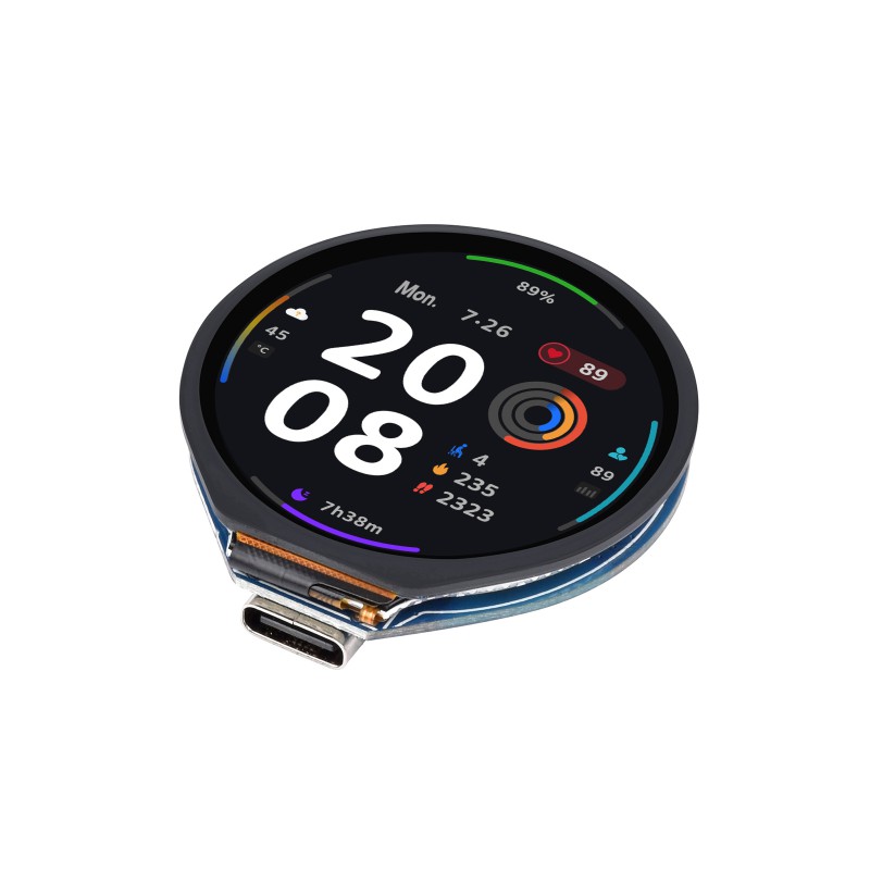
| Part | What it does | Price | Link |
|---|---|---|---|
| Waveshare ESP32-S3 Touch LCD 1.28” Round | The brain + screen + touch, all on one board. | ~$20 | Buy |
| 3.7V 250mAh LiPo Battery | Powers the watch when unplugged. Fits behind the display. | ~$5 | Buy |
| USB-C cable | Programs the board and charges the battery. | ~$5 | Buy |
| Watch strap (22mm universal) | Holds the watch on your wrist. Any standard 22mm band works. | ~$8 | Buy |
Total: ~$38 | Time: ~3-4 hours | Difficulty: ●●●○○
The board has a built-in battery connector (JST 1.25mm). The 250mAh LiPo fits neatly behind the display and gives you several hours of use.
Step 1: Set up Arduino IDE for ESP32-S3
Time: ~15 minutes
The ESP32-S3 chip needs a board package that does not come with Arduino by default. You will install it now.
- Open Arduino IDE (version 2.x recommended — download here).
- Go to File → Preferences and add this URL to “Additional boards manager URLs”:
https://raw.githubusercontent.com/espressif/arduino-esp32/gh-pages/package_esp32_index.json - Go to Tools → Board → Boards Manager, search for
esp32, and install the package by Espressif Systems (version 2.x or later). - Select Tools → Board → ESP32S3 Dev Module.
- Set Tools → USB CDC On Boot → Enabled (important for serial output).
Next, install the display library. Go to Sketch → Include Library → Manage Libraries, search for LovyanGFX, and install it. This library works perfectly with the Waveshare round display and is much faster than the default Adafruit GFX.
For full official setup docs, see the Waveshare wiki for this board.
Check: Under Tools → Board, you see “ESP32S3 Dev Module” selected. Under Tools → USB CDC On Boot, you see “Enabled.” LovyanGFX appears in Sketch → Include Library.
Step 2: Wire the display
Time: ~1 minute
Here is the best part: there is no wiring. The Waveshare ESP32-S3 1.28” board has the display, touchscreen, ESP32-S3 chip, LiPo charging circuit, and USB-C port all on a single PCB. Just plug it into your computer with a USB-C cable and you are ready to program it.
Plug in the LiPo battery to the JST connector on the back. The board charges it automatically when USB-C is connected.
Check: The board powers on when you plug in USB-C. You might see a blank white screen or a demo — that is normal.
If you want to add external sensors later (like an accelerometer for step counting), you can use the small solder pads on the back of the board. It exposes I2C, SPI, and GPIO pins, but for this tutorial you do not need any of them.
Step 3: Upload the watch face code
Time: ~10 minutes
This is the core of the project. Copy the code below into Arduino IDE, change two lines (your WiFi name and password), and hit upload.
Before uploading: Change
YOUR_WIFI_NAMEandYOUR_WIFI_PASSWORDon lines 6-7 to your real WiFi network name and password. Also setGMT_OFFSETto your timezone in seconds (for example,3600for UTC+1,-18000for UTC-5).
#define LGFX_USE_V1
#include <LovyanGFX.hpp>
#include <WiFi.h>
#include <time.h>

const char* WIFI_SSID = "YOUR_WIFI_NAME";
const char* WIFI_PASS = "YOUR_WIFI_PASSWORD";

const char* NTP_SERVER   = "pool.ntp.org";
const long  GMT_OFFSET   = 0;
const int   DAYLIGHT_ADJ = 3600;

class LGFX : public lgfx::LGFX_Device {
  lgfx::Panel_GC9A01  _panel_instance;
  lgfx::Bus_SPI       _bus_instance;

public:
  LGFX() {
    {
      auto cfg = _bus_instance.config();
      cfg.spi_host = SPI2_HOST;
      cfg.spi_mode = 0;
      cfg.freq_write = 80000000;
      cfg.pin_sclk   = 10;
      cfg.pin_mosi   = 11;
      cfg.pin_miso   = -1;
      cfg.pin_dc     = 8;
      _bus_instance.config(cfg);
      _panel_instance.setBus(&_bus_instance);
    }
    {
      auto cfg = _panel_instance.config();
      cfg.pin_cs    = 9;
      cfg.pin_rst   = 14;
      cfg.pin_busy  = -1;
      cfg.memory_width  = 240;
      cfg.memory_height = 240;
      cfg.panel_width   = 240;
      cfg.panel_height  = 240;
      cfg.offset_x      = 0;
      cfg.offset_y      = 0;
      cfg.offset_rotation = 0;
      cfg.dummy_read_pixel = 8;
      cfg.readable = false;
      cfg.invert   = true;
      cfg.rgb_order = false;
      cfg.dlen_16bit = false;
      cfg.bus_shared = false;
      _panel_instance.config(cfg);
    }
    setPanel(&_panel_instance);
  }
};

LGFX display;

#define BG_COLOR    0x0000
#define TIME_COLOR  0xFFFF
#define DATE_COLOR  0x7BEF
#define ACCENT_COLOR 0x07FF

struct tm prevTime = {};
bool timeSynced = false;

void connectWiFi() {
  display.fillScreen(BG_COLOR);
  display.setTextColor(DATE_COLOR);
  display.setTextDatum(middle_center);
  display.setTextSize(2);
  display.drawString("Connecting...", 120, 120);

  WiFi.begin(WIFI_SSID, WIFI_PASS);
  int attempts = 0;
  while (WiFi.status() != WL_CONNECTED && attempts < 20) {
    delay(500);
    attempts++;
  }
}

void syncTime() {
  configTime(GMT_OFFSET, DAYLIGHT_ADJ, NTP_SERVER);
  struct tm t;
  if (getLocalTime(&t)) {
    timeSynced = true;
  }
}

void drawWatchFace(struct tm &t) {
  display.fillScreen(BG_COLOR);

  display.drawCircle(120, 120, 118, ACCENT_COLOR);
  display.drawCircle(120, 120, 117, ACCENT_COLOR);

  char timeBuf[6];
  snprintf(timeBuf, sizeof(timeBuf), "%02d:%02d", t.tm_hour, t.tm_min);
  display.setTextColor(TIME_COLOR);
  display.setTextDatum(middle_center);
  display.setTextSize(4);
  display.drawString(timeBuf, 120, 105);

  char secBuf[3];
  snprintf(secBuf, sizeof(secBuf), "%02d", t.tm_sec);
  display.setTextColor(ACCENT_COLOR);
  display.setTextSize(2);
  display.drawString(secBuf, 120, 148);

  const char* days[]   = {"Sun","Mon","Tue","Wed","Thu","Fri","Sat"};
  const char* months[] = {"Jan","Feb","Mar","Apr","May","Jun",
                           "Jul","Aug","Sep","Oct","Nov","Dec"};
  char dateBuf[16];
  snprintf(dateBuf, sizeof(dateBuf), "%s %d %s",
           days[t.tm_wday], t.tm_mday, months[t.tm_mon]);
  display.setTextColor(DATE_COLOR);
  display.setTextSize(1);
  display.drawString(dateBuf, 120, 175);

  if (!timeSynced) {
    display.setTextColor(0xF800);
    display.drawString("NO SYNC", 120, 195);
  }
}

void setup() {
  Serial.begin(115200);

  display.init();
  display.setRotation(0);
  display.setBrightness(128);

  connectWiFi();
  syncTime();
}

void loop() {
  struct tm t;
  if (!getLocalTime(&t)) {
    delay(1000);
    return;
  }

  if (t.tm_sec != prevTime.tm_sec ||
      t.tm_min != prevTime.tm_min ||
      t.tm_hour != prevTime.tm_hour) {
    drawWatchFace(t);
    prevTime = t;
  }

  delay(200);
}
To upload:
- Hold the BOOT button on the board, press RESET once, then release BOOT.
- Select the correct COM port in Arduino IDE.
- Click the upload arrow.
Check: The board reboots, shows “Connecting…” on the round display, then shows the current time with a cyan border. If you see the time — it works. If you see “NO SYNC” in red, check the Troubleshooting table at the bottom.
Line-by-line: what every line does and why
Here is the big picture first. This program has four jobs: (1) it configures the round display hardware by describing every SPI pin to the LovyanGFX library, (2) it connects to WiFi and shows “Connecting…” while it waits, (3) it asks a time server on the internet for the exact current time (this is called NTP — the same system your computer uses), and (4) it draws hours, minutes, seconds, and date on the screen every time the second changes. The trick for battery life: the screen only redraws when something actually changed, not 60 times per second.
Lines 1-4: Loading the toolboxes
#define LGFX_USE_V1
#include <LovyanGFX.hpp>
#include <WiFi.h>
#include <time.h>
#define LGFX_USE_V1 is a signal to LovyanGFX to use its newer version 1 code. Think of it as telling a toolkit “use the 2024 edition, not the old one.” #include means “grab this instruction book” — it loads three toolboxes: LovyanGFX (all the drawing commands), WiFi (everything needed to connect to a router), and time.h (functions for handling clocks, time zones, and calendar dates). These come with the ESP32 board package — you do not need to install them separately.
Lines 6-11: WiFi and time zone settings
const char* WIFI_SSID = "YOUR_WIFI_NAME";
const char* WIFI_PASS = "YOUR_WIFI_PASSWORD";

const char* NTP_SERVER   = "pool.ntp.org";
const long  GMT_OFFSET   = 0;
const int   DAYLIGHT_ADJ = 3600;
const char* means “a piece of text that never changes” — it stores a string (a sequence of characters). Think of it as a label on a jar: the label says what is inside, and you cannot swap the contents. WIFI_SSID and WIFI_PASS are your network’s name and password. NTP_SERVER is the address of a time server on the internet — pool.ntp.org is a public pool of thousands of clocks around the world that give out the exact time for free. GMT_OFFSET is your distance from UTC in seconds: UTC+1 = 3600, UTC-5 = -18000. long means “a whole number that can be really big.” DAYLIGHT_ADJ (an int, which means “whole number”) adds an extra hour during summer time in your country (set to 0 if you do not have daylight saving time).
Lines 13-57: The LGFX display blueprint
class LGFX : public lgfx::LGFX_Device {
  lgfx::Panel_GC9A01  _panel_instance;
  lgfx::Bus_SPI       _bus_instance;
  ...
};
This is the most complex-looking block in the program, but it is just a configuration form — like filling out a delivery form telling the courier exactly which truck, which route, and which door to use. class creates a blueprint (a plan for building something). LGFX is the name we give that blueprint. public lgfx::LGFX_Device means “this blueprint is based on an existing one from the library” — like making a custom pizza by starting with a base recipe and changing the toppings.
Panel_GC9A01 is the specific display chip on this board (GC9A01 is its model number — every screen has one). Bus_SPI is the communication method — SPI is a high-speed 4-wire connection used for displays, like a highway with 4 lanes.
Inside the constructor (the function that runs automatically when you create an LGFX object — think of it as the assembly instructions that run when you open the box), cfg.spi_host = SPI2_HOST picks which of the ESP32’s two SPI controllers to use. cfg.freq_write = 80000000 sets the communication speed to 80 MHz — fast enough to redraw 240x240 pixels without flickering. cfg.pin_sclk = 10, cfg.pin_mosi = 11, etc. are the physical GPIO pin numbers where the display is connected on this specific board. cfg.pin_miso = -1 means “no pin” — this display only receives data, it never sends any back. cfg.invert = true is a quirk of the GC9A01 chip: it stores colors inverted internally, so LovyanGFX flips them to get the right colors. setPanel(&_panel_instance) connects the bus and panel together.
You do not need to change any of this — it is the permanent wiring map for the Waveshare board.
Line 59 and the color definitions
LGFX display;

#define BG_COLOR    0x0000
#define TIME_COLOR  0xFFFF
#define DATE_COLOR  0x7BEF
#define ACCENT_COLOR 0x07FF
LGFX display creates one display object using the blueprint above — like stamping one part from a mold. Now display is a variable (a named box) that holds everything you need to draw on screen.
The #define lines create named color shortcuts. #define means “every time you see this name in the code, swap it out for this value before compiling.” Colors here use RGB565 format: 16-bit numbers (numbers made of 16 ones and zeros) encoding red, green, and blue. 0x0000 is pure black (all zeros). 0xFFFF is pure white (all ones). 0x7BEF is light grey. 0x07FF is cyan (maximum green + maximum blue, no red). Using named shortcuts instead of raw hex numbers makes the code readable and easy to change — if you want a red accent, just change one line.
Lines 66-67: Remembering the previous time
struct tm prevTime = {};
bool timeSynced = false;
struct tm is a built-in C structure (think of it as a filing card with labeled fields) that holds a full date and time — year, month, day, hour, minute, second all in one variable. prevTime stores the last time the screen was drawn — so the program knows if anything changed. = {} fills every field with zero.
bool means a yes/no switch — it can only be true or false. timeSynced = false starts in the OFF position. It flips to true once the clock successfully gets the time from the internet. If it stays false, the watch draws “NO SYNC” in red so you know something went wrong.
Lines 69-82: connectWiFi() — the connection sequence
void connectWiFi() {
  display.fillScreen(BG_COLOR);
  display.drawString("Connecting...", 120, 120);

  WiFi.begin(WIFI_SSID, WIFI_PASS);
  int attempts = 0;
  while (WiFi.status() != WL_CONNECTED && attempts < 20) {
    delay(500);
    attempts++;
  }
}
void means “this function does not give back a value — it just does its job and finishes.” display.fillScreen(BG_COLOR) paints the entire 240x240 circle black — a clean slate. display.setTextDatum(middle_center) tells the library that coordinates you give are the center of the text, not the top-left corner. display.drawString("Connecting...", 120, 120) draws text centered at pixel (120, 120) — the exact middle of the round screen (240 / 2 = 120).
WiFi.begin(WIFI_SSID, WIFI_PASS) starts the connection process (like pressing “Connect” on your phone’s WiFi settings). The while loop then waits: WiFi.status() != WL_CONNECTED means “as long as we are NOT connected yet.” != means “is not equal to.” It checks every 500 milliseconds (delay(500)) up to 20 times (10 seconds total). int attempts = 0 creates a counter box starting at zero. attempts++ adds 1 to that counter each time through the loop. If the router does not respond in 10 seconds, it gives up and continues — the watch face will show “NO SYNC.”
Lines 84-90: syncTime() — asking the internet for the time
void syncTime() {
  configTime(GMT_OFFSET, DAYLIGHT_ADJ, NTP_SERVER);
  struct tm t;
  if (getLocalTime(&t)) {
    timeSynced = true;
  }
}
configTime() sends a request to pool.ntp.org saying “give me the current UTC time, then add GMT_OFFSET and DAYLIGHT_ADJ seconds to get local time.” struct tm t creates a temporary filing card to receive the answer. getLocalTime(&t) fills that card in — the & means “here is the address of this variable, write directly into it” (like handing someone a blank form and saying “fill this in for me”). if checks whether that worked. If it did, timeSynced flips to true. The ESP32’s built-in clock then keeps ticking on its own without needing the internet again.
Lines 92-125: drawWatchFace() — the painter
void drawWatchFace(struct tm &t) {
  display.fillScreen(BG_COLOR);
  display.drawCircle(120, 120, 118, ACCENT_COLOR);
  display.drawCircle(120, 120, 117, ACCENT_COLOR);

  char timeBuf[6];
  snprintf(timeBuf, sizeof(timeBuf), "%02d:%02d", t.tm_hour, t.tm_min);
  display.drawString(timeBuf, 120, 105);
  ...
}
struct tm &t receives the time filing card by reference — the & means the function works directly on the original variable without making a copy (faster, saves memory — like pointing at a whiteboard instead of photocopying it). display.drawCircle(120, 120, 118, ACCENT_COLOR) draws a cyan ring: center at (120, 120), radius 118 pixels. Two circles at radii 118 and 117 make a thicker border — like drawing a circle twice with a slightly different size.
char timeBuf[6] creates a shelf (an array) with 6 character slots — enough for “HH:MM” plus a zero terminator (a special invisible character that marks the end of text in C). snprintf(timeBuf, sizeof(timeBuf), "%02d:%02d", t.tm_hour, t.tm_min) formats the time into that shelf. snprintf is like a print command that writes to a variable instead of the screen. %02d means “print a whole number (d for decimal) with at least 2 digits, padded with a leading zero if needed” — so 9 becomes “09.” t.tm_hour reaches into the tm filing card and pulls out the hour field.
display.setTextSize(4) sets text to 4x scale — large enough to read across a room. display.drawString(timeBuf, 120, 105) draws the formatted time string centered at y=105 (slightly above center to leave room for seconds below).
The seconds and date sections follow the same pattern with different sizes, colors, and y positions.
const char* days[] = {"Sun","Mon",...} creates an array (a shelf with numbered slots) of 7 text labels — one name per day. days[t.tm_wday] picks the right name using the day-of-week number (0=Sunday, 1=Monday, and so on). Same idea for months. snprintf(dateBuf, ..., "%s %d %s", days[t.tm_wday], t.tm_mday, months[t.tm_mon]) builds a string like “Tue 7 Oct.” The %s means “insert text here” and %d means “insert a number here.”
The if (!timeSynced) block at the end draws “NO SYNC” in red (0xF800) if the time server could not be reached. ! means NOT — so !timeSynced means “if timeSynced is false.”
Lines 127-135: setup() — the morning routine (runs once)
void setup() {
  Serial.begin(115200);
  display.init();
  display.setRotation(0);
  display.setBrightness(128);
  connectWiFi();
  syncTime();
}
setup() is the morning routine — it runs exactly once when the board powers on, then never again. Serial.begin(115200) opens the USB debug line at 115,200 baud (characters per second) so you can see messages in the Serial Monitor while testing — like a hidden walkie-talkie between your board and your computer. display.init() sends wake-up commands to the GC9A01 chip. display.setRotation(0) means no rotation — pixel (0,0) is top-left. display.setBrightness(128) sets the backlight to 50% (range 0-255) — bright enough to read, easy on battery. Then connectWiFi() and syncTime() run once in order.
Lines 137-150: loop() — the heartbeat (runs forever)
void loop() {
  struct tm t;
  if (!getLocalTime(&t)) {
    delay(1000);
    return;
  }

  if (t.tm_sec != prevTime.tm_sec ||
      t.tm_min != prevTime.tm_min ||
      t.tm_hour != prevTime.tm_hour) {
    drawWatchFace(t);
    prevTime = t;
  }

  delay(200);
}
loop() is the heartbeat — it runs over and over, forever, as fast as the chip can go. First it tries getLocalTime(&t) to read the current time into a fresh filing card. If that fails (clock not set yet), return exits the function immediately and tries again in 1 second. ! means NOT — !getLocalTime means “if getLocalTime returned false.”
The if condition with || (OR — “if this OR that OR the other thing is true”) checks whether anything has changed since the last redraw: if the second, minute, OR hour is different from prevTime, it redraws the screen. This is the key efficiency trick — drawWatchFace() is expensive (it repaints the whole 240x240 circle), so we only call it once per second, not 5 times per second. prevTime = t saves the current time so the next loop can compare against it. delay(200) pauses for 200 milliseconds, making the loop check 5 times per second — fast enough to catch every second change, slow enough not to waste battery.
The whole thing in one sentence
At startup, setup() initializes the display, connects WiFi, and syncs the time; then loop() checks the clock 5 times per second and redraws the watch face exactly once each time the second ticks.
First thing to try: Upload and watch it connect. If the display shows “NO SYNC” in red, check that your WiFi name and password are exactly right (they are case-sensitive — “MyWifi” is not the same as “mywifi”). If it connects but shows the wrong time, change GMT_OFFSET to your UTC offset in seconds and re-upload.
Step 4: Add more features
The basic watch face is working — now make it smarter. Each idea below is a separate project you can add one at a time.
Step counter (concept)
The ESP32-S3 does not have a built-in accelerometer, but you can add an MPU-6050 (about $2) via I2C. I2C is a 2-wire connection — like SPI’s simpler cousin, good for small sensors. A simple step counter counts the number of times acceleration spikes above a threshold:
This is pseudocode (a sketch of the idea, not a complete program) — it requires the MPU6050 library and sensor wiring to run.
float accelMagnitude = sqrt(ax*ax + ay*ay + az*az);
if (accelMagnitude > STEP_THRESHOLD && !stepDetected) {
  stepCount++;
  stepDetected = true;
}
if (accelMagnitude < STEP_THRESHOLD - HYSTERESIS) {
  stepDetected = false;
}
float means “a number with decimal points” (like 9.81 or 3.14). sqrt calculates the square root. Display stepCount on the watch face as a small number near the bottom.
Weather from an API
Use the free Open-Meteo API — no API key needed. Make an HTTP GET request every 10 minutes:
Replace the latitude/longitude coordinates in the URL with your own city’s coordinates (find them on Google Maps).
#include <HTTPClient.h>
#include <ArduinoJson.h>
String url = "https://api.open-meteo.com/v1/forecast"
"?latitude=48.15&longitude=17.11"
"¤t_weather=true";
HTTPClient http;
http.begin(url);
int code = http.GET();
if (code == 200) {
String body = http.getString();
StaticJsonDocument<512> doc;
deserializeJson(doc, body);
float temp = doc["current_weather"]["temperature"];
}
http.end();Notification display
If you want to push text from your phone, pair the watch with a BLE app (like nRF Connect). The ESP32-S3 supports Bluetooth Low Energy out of the box:
#include <BLEDevice.h>
#include <BLEServer.h>
#include <BLEUtils.h>
#include <BLE2902.h>
This sets up a BLE UART service — your phone sends text and the watch displays it. For the full working example, search “ESP32 BLE UART” on GitHub. A full BLE implementation is its own tutorial, but the concept is straightforward: your phone sends a string, the ESP32 receives it and draws it on screen.
Step 5: Put it in a case
A bare PCB on your wrist works, but a case makes it a real product.
Option A: 3D printed case (best result)
Search Thingiverse for “ESP32 round display watch case” or “GC9A01 watch enclosure.” Several community designs fit the Waveshare board and include a back plate to hold the LiPo battery. You need access to a 3D printer (school makerspaces usually have one).
Tips for printing:
- Print in PETG or ASA for durability — PLA can warp if the watch gets warm
- Use 0.2mm layer height for a smooth finish
- Print the strap lugs at 22mm to fit standard watch bands
Option B: Sugru / moldable glue
Sugru (a silicone putty that hardens overnight) lets you build a custom bumper around the board without any printing. Mold it around the edges of the PCB, press in a 22mm strap loop on each side, and let it cure. It is waterproof and surprisingly tough.
Option C: Rubber band prototype
For testing, a wide rubber band through the PCB mounting holes holds everything together while you iterate on the software. Not glamorous, but fast.
What just happened
You just built a WiFi-connected, time-syncing, wearable computer for $38. Here is what you actually learned along the way:
-
NTP time synchronization — your watch asked a server on the internet “what time is it?” and set its own clock. This is exactly how your phone, your laptop, and every server in the world keeps time. Without NTP, every clock would slowly drift — your watch might be 5 minutes off after a week. NTP fixes that in one request.
-
SPI communication — your code told the ESP32 exactly which wires carry data to the display and how fast to send it (80 million bits per second). SPI is one of the two main ways chips talk to each other. Think of it like a one-way highway with multiple lanes — the display only listens, never talks back.
-
Efficient rendering — instead of redrawing the screen constantly, your code checks “did anything change?” and only redraws when the second ticks. This is the same trick video games use: do not repaint what has not changed. It saves battery and prevents flickering.
-
Structs as data containers —
struct tmbundles year, month, day, hour, minute, and second into one package. Without structs, you would need six separate variables. With a struct, you pass one filing card around. This is how real programs organize data. -
The setup/loop pattern —
setup()runs once (connect WiFi, start the display), thenloop()runs forever (check time, redraw if needed). Almost every Arduino program follows this pattern. It is like: wake up, do your morning routine once, then repeat your daily routine until bedtime.
Level Up
Custom analog watch face: Replace the digital time with real clock hands using drawLine() and basic trigonometry. The hour hand angle = (hour % 12) * 30 + minute * 0.5 degrees. The round display makes an analog face look surprisingly professional.
Pomodoro study timer: Build a 25-minute focus timer with a circular progress ring. Use drawArc() to draw a colored arc that shrinks as time passes. When it hits zero, flash the screen and buzz the board’s built-in LED.
Multi-screen menu: Use the built-in touchscreen to swipe between screens — clock, weather, step counter, timer. Store the current screen in an int variable (0=clock, 1=weather, 2=steps) and draw different content based on which screen is active.
Deep sleep alarm clock: Use esp_deep_sleep() to shut down the ESP32 overnight and save battery. Set a wake-up timer for your alarm time. When it wakes, flash the display and vibrate a small coin motor connected to a GPIO pin. Battery life goes from hours to days.
Troubleshooting
| Problem | Fix |
|---|---|
| Display stays white/blank after upload | Hold BOOT, press RESET, release BOOT, then upload again. Some boards need this every time. |
| “NO SYNC” shows in red | Your WiFi credentials are wrong. Check: exact name (case-sensitive), correct password, router is on and in range. |
| Time shows but wrong timezone | Change GMT_OFFSET to your UTC offset in seconds. UTC+1 = 3600. UTC-5 = -18000. UTC+5:30 = 19800. Re-upload. |
| Arduino IDE says “No port available” | Try a different USB cable — charge-only cables have no data wires. This is the number one problem. |
| Board not recognized in Boards Manager | Make sure you added the Espressif URL in File -> Preferences. Restart Arduino IDE after adding it. |
| LovyanGFX compile error | Check that you selected “ESP32S3 Dev Module” (not regular ESP32). Check that LovyanGFX is installed in Library Manager. |
| Screen flickers or shows garbage | The SPI pin numbers in the code are specific to this Waveshare board. If you have a different board, you need different pin numbers. |
| Battery does not charge | The JST connector has polarity. Try flipping the plug 180 degrees. Check that the battery is 3.7V LiPo, not something else. |