Parent info
Parts you need
Affiliate links — we may earn a small commission
Try this circuit in your browser!
Run the code, press the buttons and watch what happens — before you buy any parts. No account needed.
Open in Simulator →A step counter watch. That you built. That lasts all day.
Imagine this: it’s Monday morning. You’re wearing a round-screen watch on your wrist. It shows 4,832 steps in big white digits with a blue progress arc filling toward your 10,000-step goal. You built that watch. It costs $43 in parts. And it runs for 25+ hours on a single charge.
Your $200 Fitbit tracks steps with the same accelerometer you’re about to use. The difference: you built yours, you own the code, and you know exactly why it works.
Total: ~$43 | Time: ~4 hours | Difficulty: ●●○○○
What you’ll need
| Part | What it does | Price |
|---|---|---|
| ESP32-S3 Dev Board | The brain. S3 preferred — lower sleep current extends battery. | ~$15 |
| Waveshare 1.28” Round Display | 240×240 circular screen. Looks right on a wrist. | ~$20 |
| MPU6050 Breakout Board | 3-axis accelerometer + gyroscope. Detects footstrike spikes. | ~$3 |
| 3.7V 250mAh LiPo Battery | Thin enough to fit inside a watch case. Charges via TP4056. | ~$5 |
You also need: a TP4056 charge board (usually $2, often bundled with the LiPo), Arduino IDE 2.x, and a USB cable.
Why ESP32-S3? It has lower sleep current than the original ESP32. With light sleep between sensor reads, you get 25+ hours on a 250mAh battery. The original ESP32 gets about 10 hours in the same configuration.
How it works (60 seconds)
The MPU6050 sits on your wrist and measures acceleration on three axes 100 times per second. Walking produces a characteristic pattern: each footstrike creates a brief spike — about 1.2g (12 m/s²) on impact, dropping back to 1g between steps.
The step detection uses a rolling average threshold: instead of a fixed number, it counts a step when acceleration exceeds the rolling average by 15%. This adapts automatically — a slow walk and a hard run both get counted correctly, without changing any settings.
The power trick: between readings, the ESP32 enters light sleep for 90ms. Current drops from 80mA to 8mA. That’s 10× better battery life. Light sleep keeps RAM intact — your step count survives — unlike deep sleep which forgets everything.
Step 0: Prepare the LiPo circuit
Time: ~10 minutes
The LiPo battery needs a charge board (TP4056) to be safe. The TP4056 handles USB charging and prevents over-discharge.
- Solder the LiPo’s red wire to TP4056 BAT+ and black wire to BAT-.
- Connect TP4056 OUT+ to your ESP32-S3’s 3.3V input (or VIN if your board has a regulator).
- Connect TP4056 OUT- to ESP32-S3 GND.
- The TP4056’s USB-C port is now your charging port.
Check: Plug a USB cable into the TP4056. The red charging LED should light. Disconnect it — the ESP32 should power on from the battery. If nothing lights up, swap OUT+ and OUT-.
Step 1: Wire it up
Time: ~10 minutes
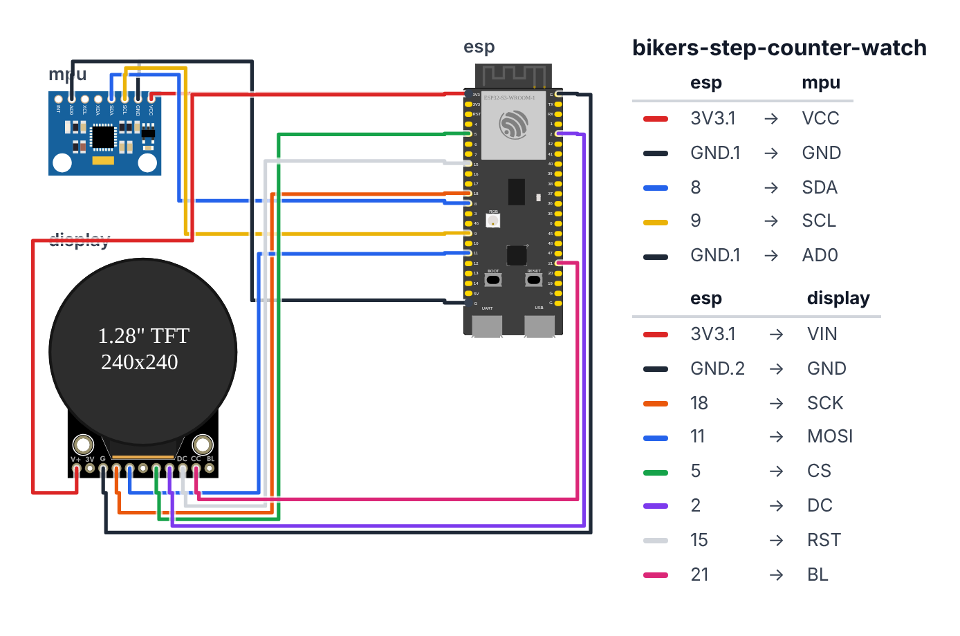
MPU6050 Accelerometer — 4 wires (I2C):
- MPU6050 VCC → ESP32-S3 3.3V — red wire
- MPU6050 GND → ESP32-S3 GND — black wire
- MPU6050 SDA → ESP32-S3 GPIO 8 (C6: GPIO 6) — blue wire
- MPU6050 SCL → ESP32-S3 GPIO 9 (C6: GPIO 7) — yellow wire
- MPU6050 AD0 → ESP32-S3 GND — black wire (sets I2C address to 0x68)
Waveshare Round Display — 8 wires (SPI): 6. Display VCC → ESP32-S3 3.3V — red wire 7. Display GND → ESP32-S3 GND — black wire 8. Display SCK → ESP32-S3 GPIO 18 (C6: GPIO 23) — orange wire 9. Display MOSI → ESP32-S3 GPIO 11 (C6: GPIO 22) — yellow wire 10. Display CS → ESP32-S3 GPIO 5 (C6: GPIO 18) — green wire 11. Display DC → ESP32-S3 GPIO 2 (C6: GPIO 10) — purple wire 12. Display RST → ESP32-S3 GPIO 15 (C6: GPIO 3) — white wire 13. Display BL → ESP32-S3 GPIO 21 (C6: GPIO 4) — pink wire
ESP32-S3         MPU6050
  3.3V ─────────── VCC
  GND  ─────────── GND
  GPIO8 ─────────── SDA  (I2C data)
  GPIO9 ─────────── SCL  (I2C clock)
  GND  ─────────── AD0  (I2C address = 0x68)

ESP32-S3         Round Display
  3.3V ─────────── VCC
  GND  ─────────── GND
  GPIO18 ─────────── SCK
  GPIO11 ─────────── MOSI
  GPIO5  ─────────── CS
  GPIO2  ─────────── DC
  GPIO15 ─────────── RST
  GPIO21 ─────────── BL
Check: The MPU6050 breakout usually has I2C pull-up resistors built in — you don’t need to add external ones. If your I2C scan shows no device at 0x68, confirm AD0 is connected to GND (not VCC, which changes the address to 0x69).
Step 2: Flash the code
Time: ~10 minutes
-
In Arduino IDE, install these libraries (Sketch > Manage Libraries):
Adafruit MPU6050by AdafruitAdafruit Unified Sensorby Adafruit (dependency — install when prompted)LovyanGFXby lovyan03
-
Copy the complete code below. Adjust
BODY_WEIGHT_KGandSTRIDE_LENGTH_Mto your values. -
Select ESP32S3 Dev Module as your board and upload.
The big picture first. This program is a step counter watch that lasts all day on a small battery.
- The MPU6050 accelerometer measures movement on three axes 100 times per second. Every footstrike creates a brief spike in acceleration — about 20% higher than the normal baseline of walking.
- Instead of a fixed trigger level, the code uses a rolling average: it counts a step when the acceleration is 15% above the recent average. This adapts automatically — a slow walk and a brisk run both register correctly.
- The battery trick: between each sensor reading, the ESP32 enters light sleep for 90ms. Current drops from 80mA to 8mA — 10 times better. Light sleep keeps RAM powered, so the step count survives. Variables tagged with
RTC_DATA_ATTRsurvive in a special low-power memory region.
// ========== CHOOSE YOUR BOARD ==========
// Uncomment the line for YOUR board:
#define BOARD_S3    // ESP32-S3-DevKitC-1
//#define BOARD_C6  // ESP32-C6-DevKitC-1
// ========================================

#ifdef BOARD_S3
  #define PIN_DISP_SCLK        18
  #define PIN_DISP_MOSI        11
  #define PIN_DISP_DC          2
  #define PIN_DISP_CS          5
  #define PIN_DISP_RST         15
  #define PIN_DISP_BL          21
  #define PIN_SDA              8
  #define PIN_SCL              9
#endif
#ifdef BOARD_C6
  #define PIN_DISP_SCLK        23
  #define PIN_DISP_MOSI        22
  #define PIN_DISP_DC          10
  #define PIN_DISP_CS          18
  #define PIN_DISP_RST         3
  #define PIN_DISP_BL          4
  #define PIN_SDA              6
  #define PIN_SCL              7
#endif

#include <Arduino.h>
#include <Wire.h>
#include <Adafruit_MPU6050.h>
#include <Adafruit_Sensor.h>
#include <LovyanGFX.hpp>
#include "esp_sleep.h"

class LGFX : public lgfx::LGFX_Device {
  lgfx::Panel_GC9A01 _panel_instance;
  lgfx::Bus_SPI      _bus_instance;
  lgfx::Light_PWM    _light_instance;
public:
  LGFX(void) {
    { auto cfg = _bus_instance.config();
      cfg.spi_host = SPI2_HOST; cfg.freq_write = 40000000;
      cfg.pin_sclk = PIN_DISP_SCLK; cfg.pin_mosi = PIN_DISP_MOSI; cfg.pin_miso = -1; cfg.pin_dc = PIN_DISP_DC;
      _bus_instance.config(cfg); _panel_instance.setBus(&_bus_instance); }
    { auto cfg = _panel_instance.config();
      cfg.pin_cs = PIN_DISP_CS; cfg.pin_rst = PIN_DISP_RST; cfg.panel_width = 240; cfg.panel_height = 240;
      _panel_instance.config(cfg); }
    { auto cfg = _light_instance.config();
      cfg.pin_bl = PIN_DISP_BL;
      _light_instance.config(cfg); _panel_instance.setLight(&_light_instance); }
    setPanel(&_panel_instance);
  }
};
static LGFX display;
Adafruit_MPU6050 mpu;

#define DAILY_STEP_GOAL   10000
#define STRIDE_LENGTH_M   0.75f
#define BODY_WEIGHT_KG    70.0f
#define STEP_THRESHOLD    1.15f
#define STEP_COOLDOWN_MS  250

RTC_DATA_ATTR int   stepCount     = 0;
RTC_DATA_ATTR float totalDistM    = 0.0f;
RTC_DATA_ATTR int   caloriesBurnt = 0;

unsigned long lastStepMs     = 0;
float         accelHistory[8] = {0};
int           histIdx        = 0;
float         rollingAvg     = 9.8f;
unsigned long lastDisplayMs  = 0;

float updateRollingAvg(float newVal) {
  accelHistory[histIdx % 8] = newVal;
  histIdx++;
  float sum = 0;
  for (int i = 0; i < 8; i++) sum += accelHistory[i];
  return sum / 8.0f;
}

void drawProgressArc(float fraction) {
  fraction = constrain(fraction, 0.0f, 1.0f);
  display.drawArc(120, 120, 117, 110, 0, 360, display.color565(30, 30, 30));
  if (fraction > 0.0f) {
    int endAngle = (int)(fraction * 360);
    uint16_t arcColor;
    if      (fraction < 0.50f) arcColor = display.color565(0,   120, 255);
    else if (fraction < 0.75f) arcColor = display.color565(0,   200, 100);
    else if (fraction < 0.90f) arcColor = display.color565(220, 180, 0);
    else                       arcColor = display.color565(255, 60,  0);
    display.drawArc(120, 120, 117, 110, 270, 270 + endAngle, arcColor);
  }
}

void drawWatchFace() {
  display.fillScreen(TFT_BLACK);

  display.setTextColor(TFT_WHITE);
  display.setTextSize(3);
  char sbuf[8]; sprintf(sbuf, "%d", stepCount);
  int textWidth = strlen(sbuf) * 18;
  display.setCursor((240 - textWidth) / 2, 95);
  display.print(sbuf);

  display.setTextColor(display.color565(150,150,150));
  display.setTextSize(1);
  display.setCursor(95, 128); display.print("steps");

  drawProgressArc((float)stepCount / (float)DAILY_STEP_GOAL);

  display.setTextColor(display.color565(100,100,100));
  display.setCursor(70, 145);
  display.print("GOAL: "); display.print(DAILY_STEP_GOAL);

  display.setTextColor(display.color565(0,180,255));
  display.setCursor(20, 175); display.print("DIST ");
  display.setTextColor(TFT_WHITE);
  char dbuf[8]; dtostrf(totalDistM / 1000.0f, 4, 2, dbuf);
  display.print(dbuf); display.print("km");

  display.setTextColor(display.color565(255,120,0));
  display.setCursor(140, 175); display.print("CAL ");
  display.setTextColor(TFT_WHITE);
  display.print(caloriesBurnt);

  display.setTextColor(display.color565(80,80,80));
  display.setCursor(80, 20); display.print("BuildCool");
}

void setup() {
  Serial.begin(115200);
  display.init();
  display.setRotation(0);
  display.setBrightness(160);

  Wire.begin(PIN_SDA, PIN_SCL);
  if (!mpu.begin()) {
    Serial.println("MPU6050 not found — check wiring. Should be at 0x68.");
    display.fillScreen(TFT_BLACK);
    display.setTextColor(TFT_RED);
    display.setCursor(30, 110); display.print("MPU6050 ERROR");
    while (1) delay(1000);
  }
  mpu.setAccelerometerRange(MPU6050_RANGE_4_G);
  mpu.setFilterBandwidth(MPU6050_BAND_21_HZ);

  drawWatchFace();
}

void loop() {
  sensors_event_t a, g, temp;
  mpu.getEvent(&a, &g, &temp);

  float ax  = a.acceleration.x;
  float ay  = a.acceleration.y;
  float az  = a.acceleration.z;
  float mag = sqrt(ax*ax + ay*ay + az*az);

  rollingAvg = updateRollingAvg(mag);

  unsigned long now = millis();
  if (mag > rollingAvg * STEP_THRESHOLD &&
      now - lastStepMs > STEP_COOLDOWN_MS) {
    lastStepMs = now;
    stepCount++;
    totalDistM    += STRIDE_LENGTH_M;
    caloriesBurnt = (int)(stepCount * STRIDE_LENGTH_M * BODY_WEIGHT_KG * 0.00063f);
  }

  if (now - lastDisplayMs > 500) {
    lastDisplayMs = now;
    drawWatchFace();
  }

  esp_sleep_enable_timer_wakeup(90000);
  esp_light_sleep_start();
}
Line-by-line: what every line does and why
Lines 1–6: Six instruction books
#include <Adafruit_MPU6050.h>
#include <Adafruit_Sensor.h>
#include "esp_sleep.h"
Adafruit_MPU6050 is the driver for the accelerometer — it handles the I2C communication and gives you clean acceleration.x, .y, .z values. Adafruit_Sensor is a dependency required by the MPU6050 library. esp_sleep.h provides the light sleep functions that extend battery life.
The RTC_DATA_ATTR variables
RTC_DATA_ATTR int   stepCount     = 0;
RTC_DATA_ATTR float totalDistM    = 0.0f;
RTC_DATA_ATTR int   caloriesBurnt = 0;
RTC_DATA_ATTR stores these variables in a special 8KB memory region inside the ESP32 that stays powered even during light sleep. Regular variables in RAM are powered off during sleep and reset to zero when the CPU wakes. These three survive the sleep — so your step count keeps going all day even though the ESP32 is “sleeping” 90ms out of every 100ms.
The settings
#define STRIDE_LENGTH_M   0.75f
#define BODY_WEIGHT_KG    70.0f
#define STEP_THRESHOLD    1.15f
#define STEP_COOLDOWN_MS  250
STRIDE_LENGTH_M is your average step distance — measure it by walking 10 steps and dividing the distance by 10. BODY_WEIGHT_KG affects calorie calculation — heavier people burn more per step. STEP_THRESHOLD = 1.15f means “count a step when acceleration is 15% above rolling average.” STEP_COOLDOWN_MS = 250 prevents one footstrike from counting as two steps — minimum 250ms between steps means maximum 4 steps per second.
updateRollingAvg(): the adaptive threshold engine
float updateRollingAvg(float newVal) {
  accelHistory[histIdx % 8] = newVal;
  histIdx++;
  float sum = 0;
  for (int i = 0; i < 8; i++) sum += accelHistory[i];
  return sum / 8.0f;
}
accelHistory[8] is an 8-slot shelf — like a window with 8 compartments. Each call adds the newest reading to histIdx % 8, which cycles through 0→1→2…→7→0→1… (the % wraps around). The function returns the average of all 8 values. As you speed up, the average rises; as you slow down, it falls. The step threshold rises and falls with you — that’s the adaptation.
setup(): initializing the accelerometer
Wire.begin(PIN_SDA, PIN_SCL);
if (!mpu.begin()) { ... }
mpu.setAccelerometerRange(MPU6050_RANGE_4_G);
mpu.setFilterBandwidth(MPU6050_BAND_21_HZ);
Wire.begin(PIN_SDA, PIN_SCL) starts I2C communication on GPIO 8 (SDA) and GPIO 9 (SCL) (C6: GPIO 6 and GPIO 7). mpu.begin() tries to find the MPU6050 at address 0x68 — if it fails, the display shows an error and the program stops. RANGE_4_G means ±4G — a footstrike is about 1.2G, well within that range. BAND_21_HZ is a low-pass filter that removes high-frequency vibration noise without affecting the 1–2Hz frequency of walking.
loop(): reading acceleration and detecting steps
float ax  = a.acceleration.x;
float ay  = a.acceleration.y;
float az  = a.acceleration.z;
float mag = sqrt(ax*ax + ay*ay + az*az);
The accelerometer gives three separate values — one per axis (like a 3D compass pointing in X, Y, Z directions). sqrt(ax²+ay²+az²) calculates the total acceleration magnitude — the length of the 3D arrow. When you’re still, this is about 9.8 m/s² (gravity). When you take a step, it briefly spikes to 11–12 m/s². This magnitude works regardless of how the watch is rotated on your wrist.
if (mag > rollingAvg * STEP_THRESHOLD &&
    now - lastStepMs > STEP_COOLDOWN_MS) {
  lastStepMs = now;
  stepCount++;
  caloriesBurnt = (int)(stepCount * STRIDE_LENGTH_M * BODY_WEIGHT_KG * 0.00063f);
}
Two conditions must both be true: the spike must be 15% above the rolling average AND at least 250ms must have passed since the last step. Both gates prevent false counts. caloriesBurnt is recalculated from scratch each time — total steps × distance per step × weight × a metabolic constant (0.00063 is the MET-based calorie factor per kg per meter).
esp_sleep_enable_timer_wakeup(90000);
esp_light_sleep_start();
Set a timer to wake up in 90,000 microseconds (90ms), then immediately sleep. The CPU halts here and draws 8mA instead of 80mA. After 90ms the timer fires, the CPU wakes, and loop() continues from the next line — calling mpu.getEvent() again for the next reading.
The whole thing in one sentence
The watch reads the accelerometer 10 times per second, counts spikes above the rolling average as steps, updates the display every 500ms, and sleeps 90ms between readings to stretch a small battery to 25+ hours.
First thing to try: flash the code, strap it to your wrist, and walk exactly 100 steps. Compare the display count — if it reads 115+, increase STEP_THRESHOLD to 1.20. If it reads below 90, decrease it to 1.10.
Check: Flash the code and walk 20 steps around the room. The display should update and show your step count. If it reads 0, check the I2C wires on GPIO 8 and 9 (C6: GPIO 6 and 7) — the MPU6050 uses I2C, not SPI.
Step 3: Tune the step detection
Time: ~10 minutes
Every body is different. Walk exactly 100 steps (count carefully) and compare to the display.
- Counter reads 115+ (too sensitive): Increase
STEP_THRESHOLDfrom 1.15 to 1.20, or increaseSTEP_COOLDOWN_MSfrom 250 to 300. - Counter reads 85 or less (misses steps): Decrease
STEP_THRESHOLDto 1.10. - Distance is wrong: Measure your actual stride — put a mark on the floor, walk 10 normal steps, measure the distance, divide by 10. That’s your
STRIDE_LENGTH_M.
Tip: Add
Serial.println("STEP " + String(stepCount));inside the step detection block and open Serial Monitor. You’ll see exactly when steps are counted as you walk. This makes tuning quick.
Step 4: Build the watch case
Time: ~30 minutes (optional but worth it)
Print or find a case. Search Printables.com for “ESP32 round display watch case” — there are a dozen options. Key tips:
- Print the main case in PETG (not PLA — your skin is warmer than PLA’s softening point on a hot day).
- Print a wrist strap connector in flexible TPU — rigid PLA is uncomfortable on a wrist.
- Leave 2mm clearance around the USB-C port on the TP4056 for charging without disassembly.
- Leave a gentle loop of display cable slack inside the case before closing — it’s the most fragile connection.
What just happened (what you learned)
-
Acceleration magnitude — the MPU6050 gives you acceleration on three separate axes. If you used just the Z-axis, the watch would only count steps when held in one orientation.
sqrt(ax²+ay²+az²)gives total acceleration regardless of wrist angle. When still, it reads ~9.8 m/s² (gravity alone). A footstrike bumps it to ~11–12 m/s². -
Rolling average adaptive threshold — instead of a fixed number like “count when acceleration > 11 m/s²”, the code uses “count when 15% above the rolling average.” A slow walk and jogging uphill have different baseline accelerations. The rolling average adapts automatically — the threshold rises with intensity and falls when you slow down.
-
Light sleep vs deep sleep — deep sleep cuts power to almost everything, including RAM. Variables are lost. Light sleep keeps RAM powered.
RTC_DATA_ATTRstores variables in a special 8KB low-power region that survives both. Trade-off: light sleep draws ~8mA (vs 0.01mA for deep sleep), but the device is ready in microseconds rather than seconds.
Level Up
Double-tap to reset daily count: The MPU6050 has a built-in tap detection interrupt. Configure mpu.setHighPassFilter(MPU6050_HIGHPASS_5_HZ) and check for the tap interrupt flag. Two taps within 500ms resets stepCount = 0, totalDistM = 0, caloriesBurnt = 0.
30-day history on SPIFFS: At midnight, append today’s final step count to a CSV file on SPIFFS: "2026-10-06,8432". Enable a temporary Wi-Fi web server on demand to serve a 30-day step history chart using Chart.js. Personal fitness archive, no cloud required.
Weatherproof for sweaty workouts: Conformal coat the PCB before assembling — sweat is more corrosive than rain. Seal all case seams with neutral-cure silicone. Add a silicone gasket around the USB port so you can charge without fully opening the case.
Troubleshooting
| Problem | Fix |
|---|---|
| “MPU6050 ERROR” on display | Check SDA → GPIO 8, SCL → GPIO 9 (C6: SDA → GPIO 6, SCL → GPIO 7), AD0 → GND. Run an I2C scanner sketch — should find device at 0x68. |
| Step count never updates | Walk vigorously and watch Serial Monitor. If no “STEP” prints, lower STEP_THRESHOLD to 1.10. |
| Step count goes up just from walking your arm | Arm swing triggers the counter. Increase STEP_THRESHOLD to 1.20 or STEP_COOLDOWN_MS to 350. |
| Battery drains in 3 hours | Confirm light sleep is working — current draw should be ~8mA. Check that esp_light_sleep_start() is called each loop. |
| Display shows nothing after charging | TP4056 output voltage may drop during charge — the display needs stable 3.3V. Confirm OUT+ is connected to the 3.3V regulator input, not a raw LiPo pin. |
| Steps disappear when power is removed | RTC_DATA_ATTR only survives light sleep and normal resets, not full power loss. That’s expected — it resets like a real pedometer. |