Parent info
Parts you need
Affiliate links — we may earn a small commission
Try this circuit in your browser!
Run the code, press the buttons and watch what happens — before you buy any parts. No account needed.
Open in Simulator →One magnet. One sensor. Your speed on a gorgeous round display.
Imagine this: a shiny circular screen on your handlebars shows 28.4 km/h in huge white digits. A colored arc around the edge fills up as you go faster — blue at a casual pace, red when you’re flying. You built that. For $35. And it tracks your max speed, average, and total distance with zero subscription fee.
That’s exactly what we’re building today. A hardware interrupt counts every wheel revolution with microsecond precision, and the math is pure physics: circumference × revolutions per second = speed.
Total: ~$35 | Time: ~3 hours | Difficulty: ●●○○○
What you’ll need
| Part | What it does | Price |
|---|---|---|
| ESP32 Dev Board | The brain. Counts pulses, does math, drives the display. | ~$12 |
| Waveshare 1.28” Round Display | Gorgeous 240×240 circular screen. Looks perfect on handlebars. | ~$20 |
| Hall Effect Sensor (A3144) | Detects when a magnet passes. One pulse per wheel revolution. | ~$2 |
| Small Neodymium Magnet (6×3mm) | Zip-tied to a spoke. Flies past the sensor once per revolution. | ~$1 |
| Jumper wires | Connects everything on the breadboard. | ~$1 |
You also need: Arduino IDE 2.x, a USB-C or micro-USB cable for flashing, and a bike.
Tip: You don’t need to solder anything to get started. Prototype on a breadboard first, then solder once it works.
How it works (60 seconds)
Think of it like a turnstile counter. Every time the magnet on your spoke passes the sensor on the fork, it sends one pulse to the ESP32. The chip records the exact time between pulses in microseconds. Speed is just your wheel’s circumference divided by the time between two pulses — pure physics, no GPS needed.
A 700c road bike wheel is about 2.1 meters around. At 60 revolutions per minute you’re going 7.5 km/h. At 500 RPM you’re flying at 63 km/h. The ESP32 calculates this every single revolution, updates the display instantly, and stores your max and average.
The magic ingredient: hardware interrupts. Instead of checking the sensor 1,000 times per second (which wastes CPU and misses pulses), you register one interrupt. When the pin goes LOW, the chip instantly drops everything, records the timestamp, and goes back to what it was doing. Total interrupt time: 1 microsecond.
Step 0: Measure your wheel
Time: ~5 minutes
Before electronics — get your wheel circumference right. This is the single most important calibration step.
- Load your bike (sit on it — your weight changes the tire’s contact patch).
- Put a chalk mark on the tire and a matching mark on the ground.
- Roll exactly one full revolution and mark the new ground position.
- Measure between the two ground marks. That is your circumference in mm.
A 700c × 25c tire is typically about 2100mm. A 26” mountain bike tire is about 2050mm. Don’t use a chart — measure yours. A 2% error compounds to 1 km wrong over a 50 km ride.
Write down your number. You’ll put it in the code as
WHEEL_CIRC_MM.
Step 1: Wire it up
Time: ~10 minutes
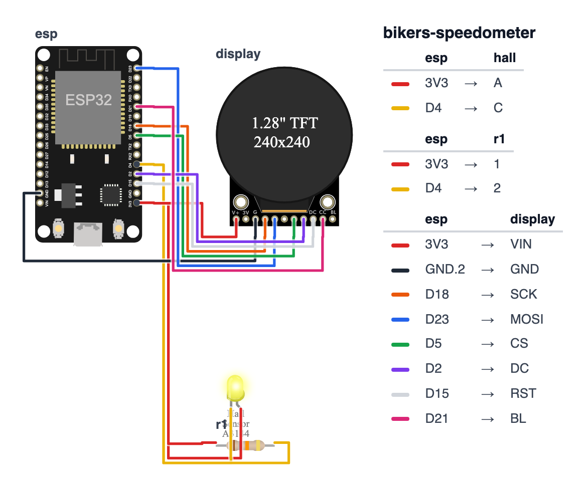
You’re connecting 11 wires total. Follow the diagram below carefully — swapping SCK and MOSI on the display will give you a blank screen.
Which board? This guide is wired for a classic ESP32 DevKit — the “ESP32 Dev Board” in the parts list. Building it on an ESP32-S3 or ESP32-C6 instead? Pick your board at the top of the code and use the pins in brackets.
Hall Effect Sensor (A3144) — 3 wires:
Hold the sensor with the flat face toward you. Left pin is VCC, middle is GND, right is OUT.
- Sensor VCC (left pin) → ESP32 3.3V — red wire
- Sensor GND (center pin) → ESP32 GND — black wire
- Sensor OUT (right pin) → ESP32 GPIO 4 (S3: GPIO 4, C6: GPIO 0) — yellow wire
- Also connect a 10kΩ resistor between GPIO 4 (S3: GPIO 4, C6: GPIO 0) and 3.3V (pull-up — keeps the pin HIGH when no magnet is present)
Waveshare Round Display — 8 wires:
- Display VCC → ESP32 3.3V — red wire
- Display GND → ESP32 GND — black wire
- Display SCK → ESP32 GPIO 18 (S3: GPIO 12, C6: GPIO 23) — orange wire
- Display MOSI → ESP32 GPIO 23 (S3: GPIO 11, C6: GPIO 22) — blue wire
- Display CS → ESP32 GPIO 5 (S3: GPIO 10, C6: GPIO 18) — green wire
- Display DC → ESP32 GPIO 2 (S3: GPIO 2, C6: GPIO 10) — purple wire
- Display RST → ESP32 GPIO 15 (S3: GPIO 15, C6: GPIO 3) — white wire
- Display BL (backlight) → ESP32 GPIO 21 (S3: GPIO 21, C6: GPIO 4) — red wire (the code uses it for PWM brightness control)
ESP32            Hall Sensor (A3144)
  3.3V ─────────── Pin 1 VCC
  GND  ─────────── Pin 2 GND
  GPIO4 ─────────── Pin 3 OUT
    │
   10kΩ pullup between GPIO4 and 3.3V

ESP32            Waveshare Round Display
  3.3V ─────────── VCC
  GND  ─────────── GND
  GPIO18 ─────────── SCK
  GPIO23 ─────────── MOSI
  GPIO5  ─────────── CS
  GPIO2  ─────────── DC
  GPIO15 ─────────── RST
  GPIO21 ─────────── BL
Check: Count your connections. You should have 3 going to the hall sensor (+ 1 resistor) and 8 going to the display. Board is NOT plugged into USB yet. Double-check GPIO 4 (S3: GPIO 4, C6: GPIO 0) is connected to the sensor OUT pin, not VCC.
Step 2: Flash the code
Time: ~10 minutes
- Open Arduino IDE. Go to Sketch > Include Library > Manage Libraries.
- Search for
LovyanGFXby lovyan03 and install it. - Copy the complete code below into a new sketch.
- Change
WHEEL_CIRC_MMto your measured number from Step 0. - Select your board: Tools > Board > ESP32 Dev Module (S3: ESP32S3 Dev Module, C6: ESP32C6 Dev Module — and pick the same board at the top of the code).
- Plug in USB and click Upload.
The big picture first. This program counts every wheel revolution and converts that count into speed, using just math and one tiny magnet.
- A neodymium magnet is zip-tied to a spoke on your wheel. Every revolution it passes a hall effect sensor mounted on the fork.
- The hall sensor sends one pulse to the ESP32 each revolution. The ESP32 records the exact time between pulses in microseconds. Speed is: wheel circumference divided by time between pulses.
- This uses a hardware interrupt — instead of checking the sensor in
loop()(which could miss pulses), the CPU immediately drops everything when the pin goes LOW, records the timestamp in 1 microsecond, and resumes. Zero pulses missed. - After 5 minutes with no movement, the ESP32 enters deep sleep drawing 10 microamps — so the battery isn’t drained while the bike is parked.
// ========== CHOOSE YOUR BOARD ==========
// Uncomment the line for YOUR board:
#define BOARD_ESP32  // classic ESP32 DevKit (ESP32-WROOM-32)
//#define BOARD_S3    // ESP32-S3-DevKitC-1
//#define BOARD_C6  // ESP32-C6-DevKitC-1
// ========================================

#ifdef BOARD_ESP32
  #define PIN_DISP_SCLK        18
  #define PIN_DISP_MOSI        23
  #define PIN_DISP_DC          2
  #define PIN_DISP_CS          5
  #define PIN_DISP_RST         15
  #define PIN_DISP_BL          21
  #define PIN_HALL             4
#endif
#ifdef BOARD_S3
  #define PIN_DISP_SCLK        12
  #define PIN_DISP_MOSI        11
  #define PIN_DISP_DC          2
  #define PIN_DISP_CS          10
  #define PIN_DISP_RST         15
  #define PIN_DISP_BL          21
  #define PIN_HALL             4
#endif
#ifdef BOARD_C6
  #define PIN_DISP_SCLK        23
  #define PIN_DISP_MOSI        22
  #define PIN_DISP_DC          10
  #define PIN_DISP_CS          18
  #define PIN_DISP_RST         3
  #define PIN_DISP_BL          4
  #define PIN_HALL             0
#endif

#include <Arduino.h>
#include <LovyanGFX.hpp>

class LGFX : public lgfx::LGFX_Device {
  lgfx::Panel_GC9A01   _panel_instance;
  lgfx::Bus_SPI        _bus_instance;
  lgfx::Light_PWM      _light_instance;
public:
  LGFX(void) {
    { auto cfg = _bus_instance.config();
      cfg.spi_host  = SPI2_HOST;
      cfg.freq_write = 40000000;
      cfg.pin_sclk  = PIN_DISP_SCLK;
      cfg.pin_mosi  = PIN_DISP_MOSI;
      cfg.pin_miso  = -1;
      cfg.pin_dc    = PIN_DISP_DC;
      _bus_instance.config(cfg); _panel_instance.setBus(&_bus_instance); }
    { auto cfg = _panel_instance.config();
      cfg.pin_cs  = PIN_DISP_CS; cfg.pin_rst = PIN_DISP_RST;
      cfg.panel_width = 240; cfg.panel_height = 240;
      _panel_instance.config(cfg); }
    { auto cfg = _light_instance.config();
      cfg.pin_bl = PIN_DISP_BL; cfg.invert = false;
      _light_instance.config(cfg); _panel_instance.setLight(&_light_instance); }
    setPanel(&_panel_instance);
  }
};
static LGFX display;

#define HALL_PIN       PIN_HALL
#define WHEEL_CIRC_MM  2100
#define MAX_SPEED_KMH  120.0f
#define SLEEP_TIMEOUT  300000

volatile unsigned long lastPulseTime    = 0;
volatile unsigned long currentPulseTime = 0;
volatile bool newPulse = false;

float currentSpeed = 0.0f;
float maxSpeed     = 0.0f;
float totalDistMm  = 0.0f;
float avgSpeed     = 0.0f;
unsigned long rideStartMs    = 0;
unsigned long lastActivityMs = 0;
int   speedSamples = 0;
float speedSum     = 0.0f;

void IRAM_ATTR hallISR() {
  unsigned long now = micros();
  if (now - currentPulseTime > 20000) {
    lastPulseTime    = currentPulseTime;
    currentPulseTime = now;
    newPulse         = true;
  }
}

void drawFace() {
  display.fillScreen(TFT_BLACK);
  display.drawCircle(120, 120, 118, display.color565(40, 40, 40));
  display.drawCircle(120, 120, 116, display.color565(40, 40, 40));
  display.setTextColor(display.color565(150, 150, 150));
  display.setTextSize(1);
  display.setCursor(105, 160); display.print("km/h");
  display.setTextColor(display.color565(100, 100, 100));
  display.setCursor(30,  185); display.print("MAX");
  display.setCursor(30,  205); display.print("AVG");
  display.setCursor(145, 185); display.print("DIST");
  display.setCursor(145, 205); display.print("TIME");
}

String formatTime(unsigned long ms) {
  unsigned long secs = ms / 1000;
  unsigned int  mins = (secs / 60) % 60;
  unsigned int  hrs  = secs / 3600;
  char buf[8];
  sprintf(buf, "%02d:%02d", hrs, mins);
  return String(buf);
}

void updateDisplay() {
  display.fillRect(40, 70, 160, 80, TFT_BLACK);

  display.setTextColor(TFT_WHITE);
  display.setTextSize(4);
  char speedBuf[6];
  dtostrf(currentSpeed, 4, 1, speedBuf);
  display.setCursor(35, 80);
  display.print(speedBuf);

  float fraction = constrain(currentSpeed / MAX_SPEED_KMH, 0.0f, 1.0f);
  int arcDeg = (int)(fraction * 270);
  display.drawArc(120, 120, 115, 110, 135, 45, display.color565(30, 30, 30));
  if (arcDeg > 0) {
    uint16_t arcColor;
    if      (currentSpeed < 20) arcColor = display.color565(0,   120, 255);
    else if (currentSpeed < 30) arcColor = display.color565(0,   200, 100);
    else if (currentSpeed < 40) arcColor = display.color565(220, 180, 0);
    else                        arcColor = display.color565(255, 60,  0);
    display.drawArc(120, 120, 115, 110, 135, 135 + arcDeg, arcColor);
  }

  display.fillRect(0, 180, 240, 60, TFT_BLACK);
  display.setTextSize(1);
  display.setTextColor(display.color565(255, 120, 0));
  display.setCursor(30, 195);
  char mbuf[6]; dtostrf(maxSpeed, 4, 1, mbuf); display.print(mbuf);
  display.setTextColor(display.color565(0, 180, 255));
  display.setCursor(30, 210);
  char abuf[6]; dtostrf(avgSpeed, 4, 1, abuf); display.print(abuf);
  display.setTextColor(display.color565(180, 255, 100));
  display.setCursor(145, 195);
  float distKm = totalDistMm / 1000000.0f;
  char dbuf[6]; dtostrf(distKm, 4, 2, dbuf); display.print(dbuf); display.print("km");
  display.setTextColor(display.color565(200, 200, 200));
  display.setCursor(145, 210);
  display.print(formatTime(millis() - rideStartMs));
}

void setup() {
  Serial.begin(115200);
  display.init();
  display.setRotation(0);
  display.setBrightness(200);

  pinMode(HALL_PIN, INPUT_PULLUP);
  attachInterrupt(digitalPinToInterrupt(HALL_PIN), hallISR, FALLING);

  rideStartMs    = millis();
  lastActivityMs = millis();
  drawFace();
  updateDisplay();
  Serial.println("Speedometer ready. Ride!");
}

void loop() {
  if (newPulse) {
    newPulse       = false;
    lastActivityMs = millis();

    unsigned long timeDeltaUs = currentPulseTime - lastPulseTime;

    if (timeDeltaUs > 50000 && timeDeltaUs < 10000000UL) {
      currentSpeed = ((float)WHEEL_CIRC_MM / (float)timeDeltaUs) * 3.6f;
      if (currentSpeed > maxSpeed) maxSpeed = currentSpeed;
      totalDistMm  += WHEEL_CIRC_MM;
      speedSum     += currentSpeed;
      speedSamples++;
      avgSpeed = speedSum / speedSamples;
    }
    updateDisplay();
  }

  if (currentSpeed > 0.0f && (micros() - currentPulseTime) > 3000000UL) {
    currentSpeed = 0.0f;
    updateDisplay();
  }

  if (millis() - lastActivityMs > SLEEP_TIMEOUT) {
    display.setBrightness(0);
    display.sleep();
    esp_deep_sleep_start();
  }

  delay(50);
}
Line-by-line: what every line does and why
The LGFX class: configuring the round display
class LGFX : public lgfx::LGFX_Device {This creates a custom display driver by extending the LovyanGFX library. Think of it like filling out a form: you tell the library which pins are SCK, MOSI, CS, DC, RST, and backlight. The library takes care of all the SPI communication after that. You fill it in once and never think about it again.
The #define settings
#define WHEEL_CIRC_MM  2100
#define SLEEP_TIMEOUT  300000
WHEEL_CIRC_MM = 2100 is your wheel circumference in millimeters — measured by rolling one revolution and measuring the distance. This is the most important number to get right: 1mm error over 100 revolutions = 10cm wrong per kilometer, compounding into kilometers of error over a long ride. SLEEP_TIMEOUT = 300000 is 5 minutes in milliseconds. After this long without a pulse, the ESP32 sleeps.
The volatile interrupt variables
volatile unsigned long lastPulseTime    = 0;
volatile unsigned long currentPulseTime = 0;
volatile bool newPulse = false;
volatile is a keyword that tells the compiler: “this variable can be changed by something outside normal program flow — never cache it.” An interrupt service routine runs outside the normal loop(), so the compiler might otherwise “optimize” an if (newPulse) check into if (false) by assuming loop() is the only thing that changes it. volatile prevents that mistake.
hallISR(): the interrupt service routine
void IRAM_ATTR hallISR() {
  unsigned long now = micros();
  if (now - currentPulseTime > 20000) {
    lastPulseTime    = currentPulseTime;
    currentPulseTime = now;
    newPulse         = true;
  }
}
IRAM_ATTR stores this function in fast internal RAM instead of slow flash memory — interrupt routines must run in microseconds. When the magnet passes and the pin goes LOW, the CPU instantly jumps here from wherever it was. micros() records the time in microseconds. The if (now - currentPulseTime > 20000) is a 20ms debounce — magnets can “bounce” as they pass, creating two pulses for one spoke revolution. 20ms filters that out without losing real pulses. newPulse = true signals to loop() that fresh data is ready.
setup(): registering the interrupt
pinMode(HALL_PIN, INPUT_PULLUP);
attachInterrupt(digitalPinToInterrupt(HALL_PIN), hallISR, FALLING);
INPUT_PULLUP pulls the pin to HIGH normally. When the magnet passes, the sensor pulls it LOW. attachInterrupt registers hallISR as the function to call when GPIO 4 (S3: GPIO 4, C6: GPIO 0) goes from HIGH to LOW (FALLING). After this line, the ESP32 never needs to check the sensor manually — the hardware handles it.
loop(): the speed formula
unsigned long timeDeltaUs = currentPulseTime - lastPulseTime;

if (timeDeltaUs > 50000 && timeDeltaUs < 10000000UL) {
  currentSpeed = ((float)WHEEL_CIRC_MM / (float)timeDeltaUs) * 3.6f;
timeDeltaUs is the time between the last two magnet pulses in microseconds. The speed formula: circumference (mm) divided by time (µs) gives mm/µs. Multiply by 3.6 converts to km/h (because 1 mm/µs = 1 km/s, and 1 km/s × 3600 = 3600 km/h… adjusted for units). The range check 50000 < timeDeltaUs < 10000000 filters out noise spikes and the very first pulse (which has no valid previous timestamp).
if (currentSpeed > 0.0f && (micros() - currentPulseTime) > 3000000UL) {
  currentSpeed = 0.0f;
  updateDisplay();
}
“If 3 seconds pass with no new pulse — the bike has stopped.” Set speed to zero and update the display. 3000000UL is 3 seconds in microseconds (UL means unsigned long — needed for large numbers).
if (millis() - lastActivityMs > SLEEP_TIMEOUT) {
  esp_deep_sleep_start();
}
After 5 minutes of no pulses, enter deep sleep. The ESP32 draws about 80mA when active. Deep sleep drops that to 10 microamps — 8,000 times less. Press the reset button to wake it.
The whole thing in one sentence
Every time the magnet passes the sensor, the ESP32 records the exact time, calculates speed from the interval, and updates the round display — and after 5 minutes of no movement it sleeps to save the battery.
First thing to try: wave a strong magnet past the hall sensor while watching Serial Monitor. The display should update with a speed reading each time the magnet passes.
Check: Open Serial Monitor (115200 baud). It should print “Speedometer ready. Ride!” — and if you wave a magnet past the sensor, you should see the display update.
Step 3: Mount it
Time: ~20 minutes
Hall sensor on the fork:
- The sensor face should sit 3–5 mm from the magnet as it passes. Closer is more reliable.
- Mount with zip ties or a 3D printed PETG fork clamp (search Thingiverse: “bike speedometer hall sensor mount”).
- The magnet goes on a spoke near the hub — less vibration than near the rim.
Display on the handlebars:
- A 31.8mm stem cap plate (search “Garmin mount 31.8mm”) is the cleanest option — replaces the stem bolt cap and costs about $5.
- 3D print an adapter plate if your display is a non-standard shape.
Check: Slowly spin the wheel by hand. Each time the magnet passes the sensor, the speed should jump on the display, then fall back to 0 after 3 seconds. If nothing happens, check that the sensor OUT pin is connected to GPIO 4 (S3: GPIO 4, C6: GPIO 0) and the pull-up resistor is in place.
Step 4: Take your first ride!
Head outside. The first time you see 24.7 km/h in huge digits on your own handlebars — that you built — is pretty satisfying.
Watch the colored arc fill up as you accelerate:
- Blue arc → you’re cruising under 20 km/h
- Green arc → solid pace, 20–30 km/h
- Yellow arc → you’re pushing it, 30–40 km/h
- Red arc → flying above 40 km/h
The bottom row shows your max speed (orange), average speed (blue), total distance (green), and ride time (white).
After 5 minutes with no wheel movement, the display goes dark and the ESP32 enters deep sleep — drawing less than 10 microamps. Touch the reset button to wake it up for your next ride.
What just happened (what you learned)
You might not realize it, but you just used three real engineering concepts:
-
Hardware interrupts — instead of checking the sensor 1,000 times per second in
loop(), you registered an ISR (Interrupt Service Routine). When the pin goes LOW, the CPU instantly pauses, jumps tohallISR(), records the timestamp in microseconds, and resumes. Total time: 1 microsecond. You never miss a pulse, no matter what else the code is doing. -
volatilevariables — when a variable is changed by an ISR (which runs outside normal program flow), you must declare itvolatile. This tells the compiler: “do not cache this in a register — always read from memory.” Without it, the compiler might optimizeif (newPulse)into “if (false)” because it never sees the main code set it to true. -
micros()vsmillis()— at 30 km/h on a 2100mm wheel, revolutions happen every 252ms —millis()is fine. But at 60 km/h revolutions happen every 126ms and timing errors compound.micros()is precise to ±1µs — essential for accurate high-speed measurements.
Level Up
Add cadence: Wire a second hall sensor to GPIO 16 (S3: GPIO 16, C6: GPIO 1) with a magnet on the crank arm. Cadence is measured exactly like speed — one pulse per revolution. Display RPM below the speed number. Cyclists optimize efficiency at 85–95 RPM — now you can see yours.
Log ride history to EEPROM: Before deep sleep, write maxSpeed, avgSpeed, totalDistMm, and ride duration to EEPROM at a fixed address. Add a button on GPIO 27 (S3: GPIO 6, C6: GPIO 11) that, when held on boot, cycles through the last 5 rides. Personal ride history, no cloud required.
Weatherproof it: Spray two coats of MG Chemicals 422B conformal coating on the PCB (mask the USB port first). Print the case in PETG. Add a silicone gasket around the seam. Result: IP54 — survives road cycling in rain.
Troubleshooting
| Problem | Fix |
|---|---|
| Display shows nothing | Check SCK → GPIO 18, MOSI → GPIO 23, DC → GPIO 2 (S3: SCK → GPIO 12, MOSI → GPIO 11, DC → GPIO 2; C6: SCK → GPIO 23, MOSI → GPIO 22, DC → GPIO 10). Swapping any of these gives a blank screen. |
| Speed is always 0 | Wave a magnet directly at the flat face of the sensor. Confirm sensor OUT → GPIO 4 (S3: GPIO 4, C6: GPIO 0) and pull-up resistor is in place. Open Serial Monitor — do you see “Speedometer ready”? |
| Speed jumps wildly | Reduce WHEEL_CIRC_MM or increase the 20000 debounce threshold in hallISR(). Check that the magnet is firmly attached to the spoke. |
| Speed reads too high or low | Re-measure your wheel circumference (loaded, one full revolution). Every mm matters over a long ride. |
| ESP32 keeps resetting | Not enough power — use a proper USB data cable, not a charge-only cable. |
| Deep sleep never wakes | Press the physical RESET button on the ESP32 board. Deep sleep wakes on hardware reset. |