Parent info
Parts you need
Affiliate links — we may earn a small commission
Try this circuit in your browser!
Run the code, press the buttons and watch what happens — before you buy any parts. No account needed.
Open in Simulator →Your route, your speed, your data — no subscription required.
Imagine this: you finish a 40 km ride, pull out the microSD card, and drag the file onto gpx.studio. Your entire route appears on a map with elevation profile, speed over every segment, and total stats. Your ESP32 logged all of it. For $46.
That’s a Garmin Edge 200 — which costs $150 and charges monthly for route exports — built for less than lunch.
Total: ~$46 | Time: ~3 hours | Difficulty: ●●○○○
What you’ll need
| Part | What it does | Price |
|---|---|---|
| ESP32 Dev Board | The brain (a classic ESP32 DevKit). Parses GPS, writes to SD, drives the display. | ~$12 |
| NEO-6M GPS Module | Receives satellite signals. Outputs speed, lat/lon, altitude, heading. | ~$8 |
| Waveshare 1.28” Round Display | Circular 240×240 screen — speed at center, compass at top. | ~$20 |
| MicroSD Card Module | Saves your GPX track file. Any 4GB+ card works. | ~$3 |
| Jumper wires | Connects everything. | ~$3 |
You also need: a FAT32-formatted microSD card (most cards come pre-formatted), Arduino IDE 2.x, and a USB cable.
How it works (60 seconds)
The NEO-6M GPS module outputs plain text called NMEA sentences at 9600 baud — one per second. A sentence like $GPRMC,123519,A,4807.038,N,01131.000,E,022.4,084.4 packs your time, position, speed, and heading into one ASCII line.
The TinyGPSPlus library reads those sentences character by character and magically gives you gps.speed.kmph(), gps.altitude.meters(), and gps.course.deg() — clean, ready-to-use numbers.
Every second when you have a GPS fix, the code writes one line to a GPX file on the SD card: your coordinates, elevation, and speed. GPX is an open XML format that every map app in the world can read. No proprietary lock-in. Your ride data is yours forever.
Why GPS speed is better than a wheel magnet for some builds: it works on any bike, trike, or cargo setup. No calibration. No magnet to fall off. The tradeoff: it takes 30–90 seconds to get a fix at startup.
Step 0: Format your SD card
Time: ~2 minutes
- Insert the microSD card into your computer.
- Format it as FAT32 (not exFAT, not NTFS).
- On Mac: Disk Utility → Erase → MS-DOS (FAT). On Windows: right-click → Format → FAT32.
Check: A freshly formatted card shows 0 bytes used. If it says “exFAT” anywhere, format it again as FAT32.
Step 1: Wire it up
Time: ~15 minutes
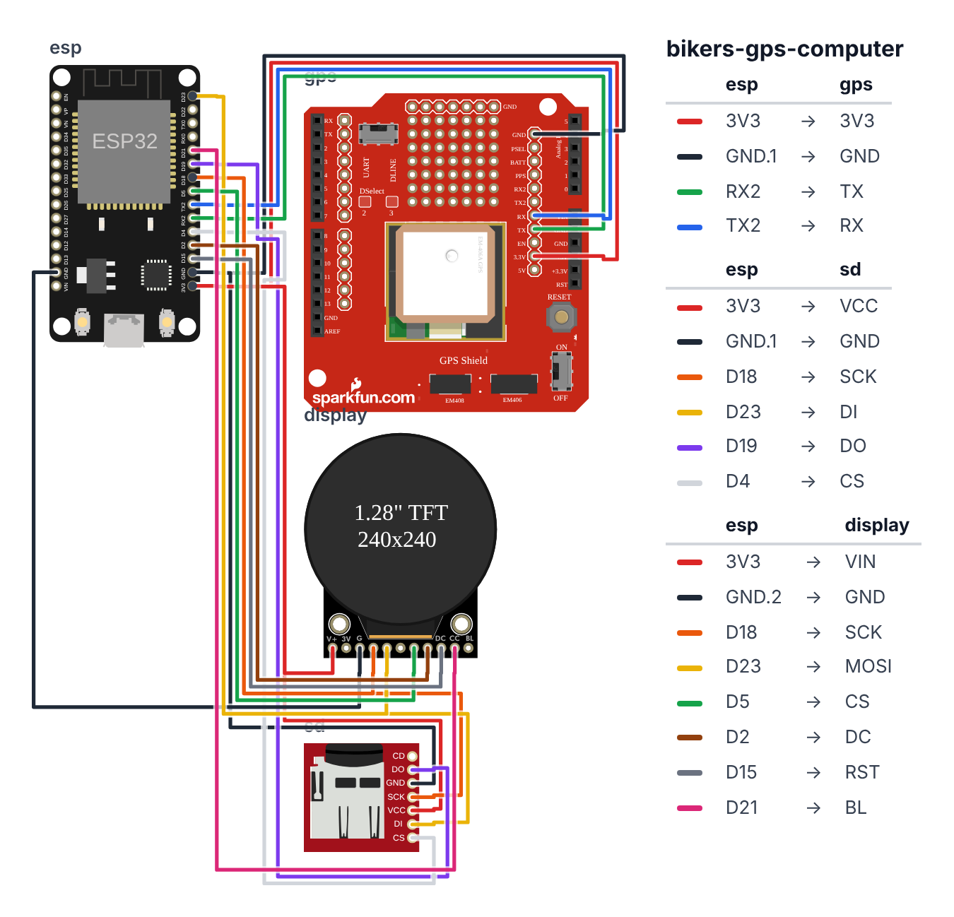
You have two SPI devices (display + SD card) sharing the same SCK/MOSI/MISO bus. This is normal — each device has its own Chip Select (CS) pin so they never talk at the same time.
Which board? This guide is wired for a classic ESP32 DevKit — the “ESP32 Dev Board” in the parts list. Building it on an ESP32-S3 or ESP32-C6 instead? Pick your board at the top of the code and use the pins in brackets. The display and SD card always sit on the board’s own SPI pins, because
SD.begin()only talks on those.
GPS Module — 4 wires (UART):
- GPS VCC → ESP32 3.3V — red wire
- GPS GND → ESP32 GND — black wire
- GPS TX → ESP32 GPIO 16 (RX2) (S3: GPIO 16, C6: GPIO 23) — green wire
- GPS RX → ESP32 GPIO 17 (TX2) (S3: GPIO 17, C6: GPIO 11) — blue wire
MicroSD Module — 6 wires (SPI): 5. SD VCC → ESP32 3.3V — red wire 6. SD GND → ESP32 GND — black wire 7. SD SCK → ESP32 GPIO 18 (S3: GPIO 12, C6: GPIO 21) — orange wire 8. SD MOSI → ESP32 GPIO 23 (S3: GPIO 11, C6: GPIO 19) — yellow wire 9. SD MISO → ESP32 GPIO 19 (S3: GPIO 13, C6: GPIO 20) — purple wire 10. SD CS → ESP32 GPIO 4 (S3: GPIO 5, C6: GPIO 22) — white wire
Waveshare Round Display — 8 wires (SPI, shared bus): 11. Display VCC → ESP32 3.3V — red wire 12. Display GND → ESP32 GND — black wire 13. Display SCK → ESP32 GPIO 18 (S3: GPIO 12, C6: GPIO 21) — orange wire (same as SD SCK) 14. Display MOSI → ESP32 GPIO 23 (S3: GPIO 11, C6: GPIO 19) — yellow wire (same as SD MOSI) 15. Display MISO → leave open (display is write-only) 16. Display CS → ESP32 GPIO 5 (S3: GPIO 10, C6: GPIO 18) — green wire (different from SD CS!) 17. Display DC → ESP32 GPIO 2 (S3: GPIO 2, C6: GPIO 10) — brown wire 18. Display RST → ESP32 GPIO 15 (S3: GPIO 15, C6: GPIO 3) — gray wire 19. Display BL → ESP32 GPIO 21 (S3: GPIO 21, C6: GPIO 4) — pink wire
ESP32            NEO-6M GPS
  3.3V ─────────── VCC
  GND  ─────────── GND
  GPIO16 ──────────── TX  (GPS transmits → ESP32 receives)
  GPIO17 ──────────── RX  (optional, for sending GPS commands)

ESP32            MicroSD Module (SPI)
  3.3V ─────────── VCC
  GND  ─────────── GND
  GPIO18 ──────────── SCK
  GPIO23 ──────────── MOSI
  GPIO19 ──────────── MISO
  GPIO4  ──────────── CS  ← SD uses GPIO4

ESP32            Waveshare Round Display (SPI — shared bus)
  GPIO18 ──────────── SCK  (same wire as SD SCK)
  GPIO23 ──────────── MOSI (same wire as SD MOSI)
  GPIO5  ──────────── CS   ← Display uses GPIO5 (different!)
  GPIO2  ──────────── DC
  GPIO15 ──────────── RST
  GPIO21 ──────────── BL
Check: SD card CS = GPIO 4 (S3: GPIO 5, C6: GPIO 22). Display CS = GPIO 5 (S3: GPIO 10, C6: GPIO 18). These MUST be different — that’s how the ESP32 knows which device to talk to. If you mix them up, you’ll get corruption or garbage on screen.
Step 2: Flash the code
Time: ~10 minutes
-
In Arduino IDE, install these libraries (Sketch > Manage Libraries):
TinyGPSPlusby Mikal HartLovyanGFXby lovyan03SDcomes built-in with the ESP32 core
-
Copy the complete code below into a new sketch.
-
Select your board and upload.
The big picture first. This program combines three things into one bike computer.
- The GPS module outputs plain text — one line per second describing your position, speed, altitude, and heading. The
TinyGPSPluslibrary reads those characters and gives you clean numbers likegps.speed.kmph(). - The round display shows your current speed in large digits, a compass arrow at the top, and stats at the bottom.
- The SD card saves every GPS position to a GPX file. GPX is an open XML format — drag it onto gpx.studio or Strava when you get home and your entire route appears on a map.
The display and SD card share the same four SPI wires (SCK, MOSI, MISO, GND). They work on one shared bus because each has its own Chip Select (CS) pin. When the ESP32 pulls GPIO 5 (S3: GPIO 10, C6: GPIO 18) LOW, the display responds. When it pulls GPIO 4 (S3: GPIO 5, C6: GPIO 22) LOW, the SD card responds. Never both at once.
// ========== CHOOSE YOUR BOARD ==========
// Uncomment the line for YOUR board:
#define BOARD_ESP32  // classic ESP32 DevKit (ESP32-WROOM-32)
//#define BOARD_S3    // ESP32-S3-DevKitC-1
//#define BOARD_C6  // ESP32-C6-DevKitC-1
// ========================================

#ifdef BOARD_ESP32
  #define PIN_DISP_SCLK        18
  #define PIN_DISP_MOSI        23
  #define PIN_DISP_MISO        19
  #define PIN_DISP_DC          2
  #define PIN_DISP_CS          5
  #define PIN_DISP_RST         15
  #define PIN_DISP_BL          21
  #define PIN_SD_CS            4
  #define PIN_GPS_RX           16
  #define PIN_GPS_TX           17
  #define DISP_SPI_HOST        SPI3_HOST  // the SPI unit SD.begin() uses on this board
#endif
#ifdef BOARD_S3
  #define PIN_DISP_SCLK        12
  #define PIN_DISP_MOSI        11
  #define PIN_DISP_MISO        13
  #define PIN_DISP_DC          2
  #define PIN_DISP_CS          10
  #define PIN_DISP_RST         15
  #define PIN_DISP_BL          21
  #define PIN_SD_CS            5
  #define PIN_GPS_RX           16
  #define PIN_GPS_TX           17
  #define DISP_SPI_HOST        SPI2_HOST  // the SPI unit SD.begin() uses on this board
#endif
#ifdef BOARD_C6
  #define PIN_DISP_SCLK        21
  #define PIN_DISP_MOSI        19
  #define PIN_DISP_MISO        20
  #define PIN_DISP_DC          10
  #define PIN_DISP_CS          18
  #define PIN_DISP_RST         3
  #define PIN_DISP_BL          4
  #define PIN_SD_CS            22
  #define PIN_GPS_RX           23
  #define PIN_GPS_TX           11
  #define DISP_SPI_HOST        SPI2_HOST  // the SPI unit SD.begin() uses on this board
#endif

#include <Arduino.h>
#include <TinyGPSPlus.h>
#include <HardwareSerial.h>
#include <SPI.h>
#include <SD.h>
#include <LovyanGFX.hpp>

class LGFX : public lgfx::LGFX_Device {
  lgfx::Panel_GC9A01 _panel_instance;
  lgfx::Bus_SPI      _bus_instance;
  lgfx::Light_PWM    _light_instance;
public:
  LGFX(void) {
    { auto cfg = _bus_instance.config();
      cfg.spi_host = DISP_SPI_HOST; cfg.freq_write = 40000000;
      cfg.pin_sclk = PIN_DISP_SCLK; cfg.pin_mosi = PIN_DISP_MOSI; cfg.pin_miso = PIN_DISP_MISO;
      cfg.pin_dc   = PIN_DISP_DC;
      _bus_instance.config(cfg); _panel_instance.setBus(&_bus_instance); }
    { auto cfg = _panel_instance.config();
      cfg.pin_cs = PIN_DISP_CS; cfg.pin_rst = PIN_DISP_RST;
      cfg.panel_width = 240; cfg.panel_height = 240;
      _panel_instance.config(cfg); }
    { auto cfg = _light_instance.config();
      cfg.pin_bl = PIN_DISP_BL;
      _light_instance.config(cfg); _panel_instance.setLight(&_light_instance); }
    setPanel(&_panel_instance);
  }
};
static LGFX display;

TinyGPSPlus    gps;
HardwareSerial gpsSerial(1);

#define SD_CS_PIN PIN_SD_CS
File   gpxFile;
bool   sdReady  = false;
bool   gpsFixed = false;

float         maxSpeedKmh = 0.0f;
unsigned long rideStartMs = 0;
unsigned long lastLogMs   = 0;
unsigned long logCount    = 0;

void openGPXFile() {
  char fname[32];
  sprintf(fname, "/ride_%lu.gpx", millis() / 1000);
  gpxFile = SD.open(fname, FILE_WRITE);
  if (gpxFile) {
    gpxFile.println("<?xml version=\"1.0\" encoding=\"UTF-8\"?>");
    gpxFile.println("<gpx version=\"1.1\" creator=\"BuildCool ESP32\">");
    gpxFile.println("<trk><name>BuildCool Ride</name><trkseg>");
    gpxFile.flush();
    sdReady = true;
    Serial.println("GPX file: " + String(fname));
  }
}

void logTrackpoint() {
  if (!sdReady || !gpxFile) return;
  char buf[200];
  sprintf(buf,
    "  <trkpt lat=\"%.6f\" lon=\"%.6f\"><ele>%.1f</ele><speed>%.2f</speed></trkpt>",
    gps.location.lat(), gps.location.lng(),
    gps.altitude.meters(),
    gps.speed.mps());
  gpxFile.println(buf);
  logCount++;
  if (logCount % 10 == 0) gpxFile.flush();
}

void drawCompass(float headingDeg) {
  float rad = headingDeg * DEG_TO_RAD;
  int cx = 120, cy = 50, r = 25;
  int tx = cx + (int)(r * sin(rad));
  int ty = cy - (int)(r * cos(rad));
  int bx = cx - (int)((r-8) * sin(rad));
  int by = cy + (int)((r-8) * cos(rad));
  display.fillCircle(cx, cy, r+2, TFT_BLACK);
  display.drawCircle(cx, cy, r, display.color565(60,60,60));
  display.fillTriangle(tx, ty, bx+5, by, bx-5, by, display.color565(255,120,0));
}

void updateDisplay() {
  float speedKmh = gps.speed.isValid() ? gps.speed.kmph() : 0.0f;

  display.fillRect(30, 90, 180, 65, TFT_BLACK);
  display.setTextColor(gpsFixed ? TFT_WHITE : display.color565(100,100,100));
  display.setTextSize(4);
  char sbuf[7]; dtostrf(speedKmh, 5, 1, sbuf);
  display.setCursor(20, 95); display.print(sbuf);
  display.setTextSize(1);
  display.setTextColor(display.color565(150,150,150));
  display.setCursor(102, 155); display.print("km/h");

  display.fillCircle(220, 15, 6,
    gpsFixed ? display.color565(0,200,0) : display.color565(200,0,0));

  if (gps.course.isValid()) drawCompass(gps.course.deg());

  display.fillRect(0, 170, 240, 70, TFT_BLACK);
  display.setTextSize(1);

  display.setTextColor(display.color565(100,100,100));
  display.setCursor(10, 175); display.print("ALT");
  display.setTextColor(TFT_WHITE);
  display.setCursor(10, 186);
  if (gps.altitude.isValid()) {
    char abuf[8]; dtostrf(gps.altitude.meters(), 5, 0, abuf);
    display.print(abuf); display.print("m");
  } else { display.print("---"); }

  display.setTextColor(display.color565(100,100,100));
  display.setCursor(90, 175); display.print("MAX");
  display.setTextColor(display.color565(255,120,0));
  display.setCursor(90, 186);
  char mbuf[7]; dtostrf(maxSpeedKmh, 5, 1, mbuf); display.print(mbuf);

  display.setTextColor(display.color565(100,100,100));
  display.setCursor(165, 175); display.print("PTS");
  display.setTextColor(display.color565(0,180,255));
  display.setCursor(165, 186); display.print(logCount);

  display.setTextColor(display.color565(150,150,150));
  display.setCursor(80, 205);
  unsigned long elapsed = (millis() - rideStartMs) / 1000;
  char tbuf[8]; sprintf(tbuf, "%02d:%02d", (int)(elapsed/3600), (int)((elapsed/60)%60));
  display.print(tbuf);

  display.setCursor(10, 205);
  display.print("SAT:");
  display.print(gps.satellites.isValid() ? gps.satellites.value() : 0);
}

void setup() {
  Serial.begin(115200);
  gpsSerial.begin(9600, SERIAL_8N1, PIN_GPS_RX, PIN_GPS_TX);

  display.init();
  display.setRotation(0);
  display.setBrightness(180);
  display.fillScreen(TFT_BLACK);
  display.setTextColor(display.color565(80,80,80));
  display.setCursor(10, 10); display.print("BuildCool GPS");

  if (!SD.begin(SD_CS_PIN)) {
    Serial.println("SD card not found — riding without logging.");
  } else {
    openGPXFile();
  }

  rideStartMs = millis();
  updateDisplay();
}

void loop() {
  while (gpsSerial.available()) {
    gps.encode(gpsSerial.read());
  }

  gpsFixed = gps.location.isValid() && gps.hdop.isValid() && gps.hdop.value() < 300;

  if (gps.speed.isValid()) {
    float sp = gps.speed.kmph();
    if (sp > maxSpeedKmh) maxSpeedKmh = sp;
  }

  if (gpsFixed && millis() - lastLogMs >= 1000) {
    lastLogMs = millis();
    logTrackpoint();
    updateDisplay();
  } else if (!gpsFixed && millis() - lastLogMs >= 2000) {
    lastLogMs = millis();
    updateDisplay();
  }
}
Line-by-line: what every line does and why
Lines 1–6: Libraries for GPS, storage, and display
#include <TinyGPSPlus.h>
#include <HardwareSerial.h>
#include <SD.h>
TinyGPSPlus reads the GPS module’s text output and gives you clean values. HardwareSerial lets us use a dedicated UART port for the GPS — faster and more reliable than software serial. SD.h provides the filesystem tools to write GPX files to the SD card.
GPS and SD setup
TinyGPSPlus    gps;
HardwareSerial gpsSerial(1);

#define SD_CS_PIN PIN_SD_CS
gps is the parser object — you feed it bytes, it assembles sentences and extracts values. gpsSerial(1) creates a connection to hardware serial port 1 (every ESP32 has one — the C6 has no port 2). gpsSerial.begin() in setup() puts it on GPIO 16 and 17 (S3: GPIO 16 and 17, C6: GPIO 23 and 11). SD_CS_PIN is PIN_SD_CS — GPIO 4 (S3: GPIO 5, C6: GPIO 22), the Chip Select for the SD card module. The display uses GPIO 5 (S3: GPIO 10, C6: GPIO 18) as its CS. These must be different — that’s how two devices share the same SPI bus.
openGPXFile(): creating a valid GPX file
gpxFile.println("<?xml version=\"1.0\" encoding=\"UTF-8\"?>");
gpxFile.println("<gpx version=\"1.1\" creator=\"BuildCool ESP32\">");
gpxFile.println("<trk><name>BuildCool Ride</name><trkseg>");
gpxFile.flush();
GPX is XML — a structured text format. The file needs an opening header before any trackpoints can be added. gpxFile.flush() writes the header to the SD card’s physical storage immediately — even if power is lost right now, the file header is already saved. Without flush(), data sits in a RAM buffer and is lost on power cut.
logTrackpoint(): writing one GPS position
sprintf(buf,
  "  <trkpt lat=\"%.6f\" lon=\"%.6f\"><ele>%.1f</ele><speed>%.2f</speed></trkpt>",
  gps.location.lat(), gps.location.lng(),
  gps.altitude.meters(),
  gps.speed.mps());
sprintf formats a string — like filling in a template. %.6f means 6 decimal places of a floating-point number. Six decimal places for latitude and longitude gives about 11 centimeters of precision — more than enough for cycling. gps.speed.mps() is meters per second — the GPX standard specifies m/s for speed.
if (logCount % 10 == 0) gpxFile.flush();% is the remainder operator — 10 % 10 = 0, 11 % 10 = 1, 20 % 10 = 0. This evaluates to true every 10 trackpoints — meaning we flush to the SD card every 10 seconds. Flushing every second would wear out the SD card’s memory faster. Every 10 seconds is a good trade-off between safety and longevity.
loop(): the GPS data pipeline
while (gpsSerial.available()) {
  gps.encode(gpsSerial.read());
}
The GPS module sends one character at a time at 9600 baud. gpsSerial.read() gets the next character. gps.encode() feeds it to the TinyGPSPlus parser, which internally assembles complete NMEA sentences. When a complete sentence arrives, it updates gps.speed, gps.location, etc. The while loop makes sure we process every character that arrived since the last loop cycle.
gpsFixed = gps.location.isValid() && gps.hdop.isValid() && gps.hdop.value() < 300;“Good fix” requires two conditions: a valid location AND good satellite geometry (HDOP below 3.0 — hdop.value() returns HDOP × 100, so 300 = 3.0). HDOP (Horizontal Dilution of Precision) measures how well the satellites are spread across the sky. Clustered satellites give poor geometry and inaccurate positions. HDOP below 3.0 means reliable accuracy.
The whole thing in one sentence
Every second with a GPS fix, the computer logs your position and elevation to a GPX file on the SD card and updates the display with speed, compass heading, max speed, altitude, satellite count, and ride time.
First thing to try: take the device outside, set it on a flat surface facing up, and watch the satellite count climb from 0 to 4+. The dot turns green when you have a good fix — that’s when logging starts. Bring the SD card home and drag the GPX file onto gpx.studio to see your position logged.
Check: Open Serial Monitor (115200 baud). You should see “BuildCool GPS” and either “GPX file: /ride_X.gpx” (SD card found) or “SD card not found.” Go outside — the display’s red dot will turn green when the GPS locks.
Step 3: Get your first GPS fix
Time: ~2 minutes outdoors
The NEO-6M needs a clear view of the sky. Walk outside, set the device on a flat surface with the GPS antenna facing up, and wait.
Watch the satellite count (SAT:) on the display climb from 0 to 4+. The indicator dot turns green when you have a good fix. Cold start (first power-on of the day) takes 30–90 seconds. After that it locks in under 10 seconds.
Common mistake: Testing GPS indoors or near a wall. The module receives satellite signals — you need sky, not ceiling. A window sometimes works but rooftops always do.
Step 4: Ride and review!
Go for a ride. The round display shows:
- Speed in huge digits at center (grey until fixed, white when live)
- Compass arrow pointing your direction of travel
- Altitude, max speed, logged point count, satellite count, and ride time at the bottom
When you get home, remove the SD card. Find the file named ride_XXXX.gpx. Drag it into any of these:
- gpx.studio — free, no account, instant route map with elevation and speed
- Google My Maps — import GPX, see your route on Google Maps
- Strava — drag the file onto the upload button
Your GPS computer. Your data. No subscription. Ever.
What just happened (what you learned)
-
NMEA sentences — GPS modules output plain ASCII text at 9600 baud. TinyGPSPlus reads them character by character inside
gps.encode()and updates its internal state when a complete sentence arrives. You never parse GPS text manually. -
HDOP (Horizontal Dilution of Precision) — GPS accuracy depends on where satellites are in the sky. Satellites clustered together give poor geometry. HDOP measures this: 1.0 = ideal, 2.0 = good, 5.0 = poor.
gps.hdop.value() < 300means HDOP < 3.0 — a solid threshold for cycling. -
Shared SPI bus — the display and SD card both use the same four SPI wires (SCK, MOSI, MISO, GND). They share those wires because each has its own Chip Select (CS) pin. GPIO 5 (S3: GPIO 10, C6: GPIO 18) pulls LOW → display talks. GPIO 4 (S3: GPIO 5, C6: GPIO 22) pulls LOW → SD card talks. Never both at once. One SPI bus, many devices.
-
GPX format — an open XML standard that every mapping app supports. By writing GPX, your ride data is portable forever. No proprietary format. No subscription to export your own files.
Level Up
Add a waypoint button: Use the board’s BOOT button — GPIO 0 (S3: GPIO 0, C6: GPIO 9) with INPUT_PULLUP — or wire your own button from that pin to GND. When pressed, write a <wpt> element to the GPX file: <wpt lat="X" lon="Y"><name>Stop</name></wpt>. Waypoints show as pins on mapping software — mark water stops, wildlife sightings, or puncture locations.
Track total elevation gain: Each new trackpoint, compare current altitude to the previous one. If it’s higher, add the difference to a totalClimbM variable. Display it in the stats row. Use a 5-sample rolling average to filter GPS noise before comparing.
Ceramic patch antenna upgrade: Replace the stock stubby antenna on the NEO-6M with a small ceramic patch antenna (connects to the IPEX connector). Cuts cold fix time from 90 seconds to under 20, and almost never loses signal under tree cover.
Troubleshooting
| Problem | Fix |
|---|---|
| GPS fix indicator never turns green | Go outside with clear sky view. Wait 90 seconds minimum. Watch satellite count — you need 4+. |
| SD card not found | Check: CS → GPIO 4, SCK → GPIO 18, MOSI → GPIO 23, MISO → GPIO 19 (S3: CS → GPIO 5, SCK → GPIO 12, MOSI → GPIO 11, MISO → GPIO 13; C6: CS → GPIO 22, SCK → GPIO 21, MOSI → GPIO 19, MISO → GPIO 20). Format card as FAT32, not exFAT. |
| Display shows garbage | Display CS is GPIO 5 (S3: GPIO 10, C6: GPIO 18), not GPIO 4 (S3: GPIO 5, C6: GPIO 22). Swap them back. |
| GPX file won’t open in Strava | File must end with </trkseg></trk></gpx> — this only writes if you reset the ESP32 cleanly (normal power loss leaves the file open but Strava still imports it). |
| Speed shows 0 even with fix | GPS speed requires movement. Walk around — it should update. Check that gps.speed.isValid() returns true in Serial Monitor. |
| GPS antenna must face sky | Mount the device with the antenna on top, not underneath a stem or inside a bag. |