Parent info
Parts you need
Affiliate links — we may earn a small commission
Try this circuit in your browser!
Run the code, press the buttons and watch what happens — before you buy any parts. No account needed.
Open in Simulator →Your GPS track on a map — with no cell signal required.
Imagine this: you’re 8 km into a trail. No phone signal. Your trail logger is quietly saving one GPS position per second to a GPX file on the SD card. At the same time, its LoRa radio is broadcasting your coordinates every 30 seconds. Your contact at home sees your blue dot moving on the Meshtastic app, with zero cellular infrastructure between you.
When you get back, you plug in the SD card and your entire route appears on a map. Elevation profile, speed, distance — all there. You built this for $36.
Total: ~$36 | Time: ~3 hours | Difficulty: ●●○○○
What you’ll need
| Part | What it does | Price |
|---|---|---|
| Heltec WiFi LoRa 32 V3 | ESP32-S3 + OLED display + LoRa radio on one PCB. The OLED and LoRa are pre-wired. You need this exact board — the pins in this guide are for the V3 (V3.2 is the one sold today; V3.0 and V3.1 work too, see the battery note in Step 3). | ~$20 |
| NEO-6M GPS Module | Better GPS accuracy than built-in positioning. Ceramic patch antenna. | ~$8 |
| MicroSD Card Module | Saves your GPX track file. FAT32-formatted. | ~$3 |
| 18650 Battery + Holder | 3000mAh cell gives 8–18 hours at low LoRa transmit rate. | ~$5 |
What is the Heltec WiFi LoRa 32 V3? It’s a development board that combines an ESP32-S3 processor, a 0.96” OLED display, and a LoRa SX1262 radio on one tiny PCB for $20. The display and LoRa radio are already soldered to fixed GPIO pins — you can’t move them. This saves you from connecting 10 extra wires. It’s the perfect board for outdoor projects.
How it works (60 seconds)
Think of this as two projects in one:
Part 1 — Route logger: The NEO-6M GPS module sends NMEA position data over UART. The code parses it and writes one trackpoint per second to a GPX file on the microSD card. When you’re done, plug the card into any computer and drag the file into a map app.
Part 2 — LoRa tracker: The Heltec board’s built-in SX1262 LoRa radio transmits your position wirelessly every 30 seconds using the Meshtastic protocol. LoRa (Long Range) can broadcast 2–15 km with no cellular network. A second Meshtastic device at your home base receives your position and shows it on a map app. Three nodes can cover a 15 km radius hop-by-hop.
LoRa is not the internet. It’s a radio signal — like walkie-talkies, but for data, and much farther range.
Step 0: Install the ESP32 board package
Time: ~5 minutes
The Heltec V3 is an ESP32-S3 board, and the standard ESP32 board package already knows it — including its OLED, LoRa and battery pins.
- Go to Tools > Board > Boards Manager, search “esp32”, and install esp32 by Espressif Systems (skip this if it’s already installed).
- Select Tools > Board > esp32 > Heltec WiFi LoRa 32(V3) — the right choice for the V3 board this guide uses. (An older V2 or V2.1 board has a different chip and different pins, so this sketch won’t run on it.)
- Plug the board in with a USB-C data cable and pick its port under Tools > Port.
Check: Create a new blank sketch and compile it. If it compiles without errors, the board package is installed correctly.
Step 1: Wire it up
Time: ~10 minutes
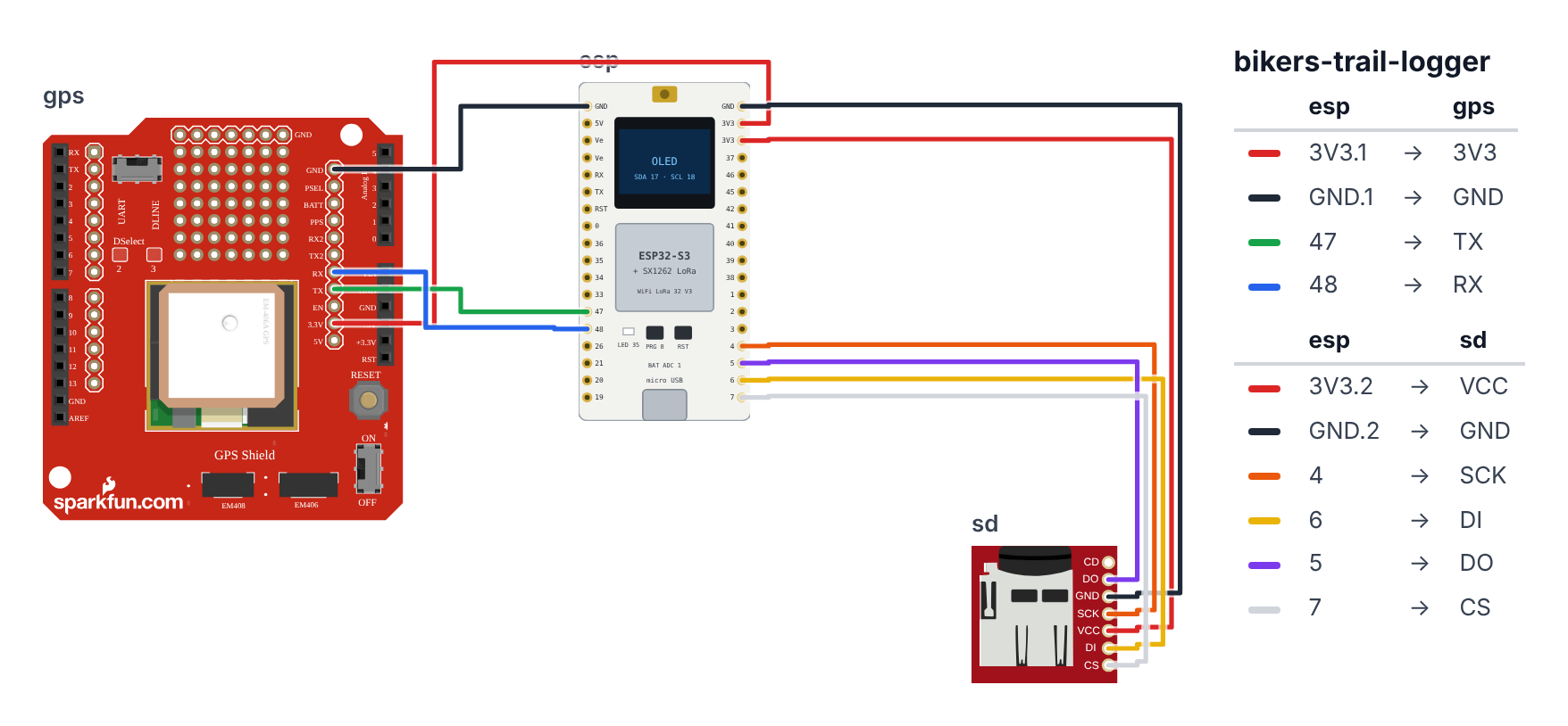
The OLED and LoRa on the Heltec are already wired internally. You’re adding the GPS module and microSD card.
Which board? This project only works on the Heltec WiFi LoRa 32 V3. An ESP32-S3 or ESP32-C6 DevKit has no LoRa radio and no built-in OLED, so the code has just one board block: Heltec V3.
External NEO-6M GPS — 4 wires (UART1):
- GPS VCC → Heltec 3V3 — red wire (the GPS module runs fine on 3.3V, and the 3V3 pins stay powered when the board runs on its battery)
- GPS GND → Heltec GND — black wire
- GPS TX → Heltec GPIO 47 — green wire (the ESP32 listens here)
- GPS RX → Heltec GPIO 48 — blue wire (the ESP32 talks here)
MicroSD Module — 6 wires (SPI): 5. SD VCC → Heltec 3V3 — red wire 6. SD GND → Heltec GND — black wire 7. SD SCK → Heltec GPIO 4 — orange wire 8. SD MOSI → Heltec GPIO 6 — yellow wire 9. SD MISO → Heltec GPIO 5 — purple wire 10. SD CS → Heltec GPIO 7 — white wire
Battery: 11. Connect the 18650 holder to the board’s small 2-pin battery socket with a 2-pin SH1.25 battery cable (one usually comes with the board): red to +, black to −. Check which side is + before you plug in — a battery the wrong way round can destroy the board.
The SD card gets its own SPI bus on GPIO 4–7. The LoRa radio has its own SPI wires inside the board, so the two never get in each other’s way.
Heltec LoRa 32 V3       NEO-6M GPS
  3V3 ─────────────────── VCC
  GND ─────────────────── GND
  GPIO47 ──────────────── TX
  GPIO48 ──────────────── RX

Heltec LoRa 32 V3       MicroSD Module (SPI)
  3V3  ─────────────────── VCC
  GND  ─────────────────── GND
  GPIO4  ───────────────── SCK
  GPIO6  ───────────────── MOSI
  GPIO5  ───────────────── MISO
  GPIO7  ───────────────── CS

OLED (SSD1306) and LoRa (SX1262)
are already wired on the Heltec PCB.
Check: Both modules get their power from a 3V3 pin (the pin row that starts GND, 3V3, 3V3 has two of them) — not from 5V or Ve.
Step 2: Quick win — Meshtastic (no coding needed)
Time: ~10 minutes
Before writing any code, try the easiest path first: Meshtastic firmware gives you LoRa position tracking with zero coding.
- Go to flasher.meshtastic.org in Chrome or Edge.
- Select Heltec V3.
- Click Flash and follow the prompts.
- Download the Meshtastic app on your phone (iOS or Android).
- Connect via Bluetooth, set your channel name, enable GPS, set transmit interval to 30 seconds.
- Tell Meshtastic where your GPS is: in the app go to Radio Configuration > Position and set GPS Receive GPIO to 47 and GPS Transmit GPIO to 48. The V3 has no GPS of its own, so it can’t guess.
That’s it. Your position broadcasts automatically. Anyone else with Meshtastic in range (or at home with a base station) sees you on a map.
Check: Open the Meshtastic app and look at the map. Your device should appear as a node after getting a GPS fix. If you see “no nodes found,” confirm the GPS antenna has sky view and wait 60 seconds.
Step 3: Flash the GPS logger code
Time: ~10 minutes
For custom GPX logging alongside Meshtastic (or instead of it), flash this code:
- Install libraries in Arduino IDE:
TinyGPSPlusby Mikal HartAdafruit SSD1306by AdafruitAdafruit GFX Libraryby Adafruit (dependency)SD— built into ESP32 core
Think of the Heltec board as a pre-assembled trail computer. The tiny OLED screen and the long-range LoRa radio are already soldered to specific pins on the PCB — you cannot move them, and the code must use those exact pin numbers. On top of that pre-built base, you plug in a NEO-6M GPS module (sends position text over a serial cable) and a microSD card slot (saves the GPX diary). The code has one job in the background: read GPS sentences character-by-character, and every time TinyGPSPlus announces “I have a complete, valid fix,” stamp that location into the GPX file on the SD card. Every 5 seconds it also redraws the OLED with 5 lines of status so you know things are working without opening a laptop.
// ========== CHOOSE YOUR BOARD ==========
// Uncomment the line for YOUR board:
#define BOARD_HELTEC_V3  // Heltec WiFi LoRa 32 V3 (the only board with the LoRa radio + OLED this project needs)
// ========================================

#ifdef BOARD_HELTEC_V3
  #define PIN_OLED_SDA         17
  #define PIN_OLED_SCL         18
  #define PIN_OLED_RST         21
  #define PIN_VEXT             36
  #define PIN_SD_CS            7
  #define PIN_SD_SCK           4
  #define PIN_SD_MISO          5
  #define PIN_SD_MOSI          6
  #define PIN_GPS_RX           47
  #define PIN_GPS_TX           48
  #define PIN_BATT_ADC         1
  #define PIN_BATT_CTRL        37
#endif

#include <Arduino.h>
#include <TinyGPSPlus.h>
#include <HardwareSerial.h>
#include <SPI.h>
#include <SD.h>
#include <Wire.h>
#include <Adafruit_SSD1306.h>

#define OLED_SDA    PIN_OLED_SDA
#define OLED_SCL   PIN_OLED_SCL
#define OLED_RST   PIN_OLED_RST
Adafruit_SSD1306 oled(128, 64, &Wire, OLED_RST);

HardwareSerial gpsSerial(1);
TinyGPSPlus    gps;

#define SD_CS PIN_SD_CS
SPIClass sdSPI(HSPI);
File logFile;
bool sdOk    = false;
bool logOpen = false;

#define LOG_INTERVAL_MS  1000
#define DISPLAY_INTERVAL 5000

unsigned long lastLogMs     = 0;
unsigned long lastDisplayMs = 0;
unsigned long trackPoints   = 0;

float readBattVoltage() {
  int mv = analogReadMilliVolts(PIN_BATT_ADC);
  return mv * 4.9f / 1000.0f;
}

void openLog() {
  char fname[32];
  sprintf(fname, "/trail_%lu.gpx", millis() / 1000);
  logFile = SD.open(fname, FILE_WRITE);
  if (logFile) {
    logFile.println("<?xml version=\"1.0\" encoding=\"UTF-8\"?>");
    logFile.println("<gpx version=\"1.1\" creator=\"BuildCool TrailLogger\">");
    logFile.println("<trk><name>Trail Log</name><trkseg>");
    logFile.flush();
    logOpen = true;
    Serial.println("Trail log: " + String(fname));
  }
}

void writeTrackpoint() {
  if (!logOpen) return;
  char buf[180];
  sprintf(buf,
    "  <trkpt lat=\"%.6f\" lon=\"%.6f\">"
    "<ele>%.1f</ele><speed>%.2f</speed></trkpt>",
    gps.location.lat(), gps.location.lng(),
    gps.altitude.meters(),
    gps.speed.mps());
  logFile.println(buf);
  trackPoints++;
  if (trackPoints % 30 == 0) logFile.flush();
}

void updateOLED() {
  oled.clearDisplay();
  oled.setTextSize(1);
  oled.setTextColor(SSD1306_WHITE);

  oled.setCursor(0, 0);
  if (gps.location.isValid()) {
    oled.print("GPS OK  SAT:"); oled.print(gps.satellites.value());
  } else {
    oled.print("GPS: searching...");
  }

  oled.setCursor(0, 12);
  oled.print("SPD: ");
  if (gps.speed.isValid()) {
    oled.print(gps.speed.kmph(), 1); oled.print(" km/h");
  } else { oled.print("---"); }

  oled.setCursor(0, 24);
  oled.print("ALT: ");
  if (gps.altitude.isValid()) {
    oled.print(gps.altitude.meters(), 0); oled.print("m");
  } else { oled.print("---"); }

  oled.setCursor(0, 36);
  oled.print("PTS: "); oled.print(trackPoints);
  oled.print(sdOk ? "  SD OK" : "  NO SD");

  oled.setCursor(0, 48);
  float vbat = readBattVoltage();
  oled.print("BAT: "); oled.print(vbat, 2); oled.print("V");

  oled.display();
}

void setup() {
  Serial.begin(115200);

  pinMode(PIN_VEXT, OUTPUT);
  digitalWrite(PIN_VEXT, LOW);
  delay(50);
  Wire.begin(OLED_SDA, OLED_SCL);
  if (oled.begin(SSD1306_SWITCHCAPVCC, 0x3C)) {
    oled.clearDisplay();
    oled.setTextSize(1);
    oled.setTextColor(SSD1306_WHITE);
    oled.setCursor(0, 20); oled.print("BuildCool TrailLogger");
    oled.setCursor(0, 35); oled.print("  Initializing...");
    oled.display();
  }

  gpsSerial.begin(9600, SERIAL_8N1, PIN_GPS_RX, PIN_GPS_TX);

  pinMode(PIN_BATT_CTRL, OUTPUT);
  digitalWrite(PIN_BATT_CTRL, HIGH);   // V3.2 board. On a V3.0 / V3.1 board: LOW
  sdSPI.begin(PIN_SD_SCK, PIN_SD_MISO, PIN_SD_MOSI, SD_CS);
  if (SD.begin(SD_CS, sdSPI)) {
    sdOk = true;
    openLog();
  } else {
    Serial.println("SD card not found — no logging.");
  }

  delay(1500);
  updateOLED();
}

void loop() {
  while (gpsSerial.available()) {
    gps.encode(gpsSerial.read());
  }

  if (gps.location.isValid() && millis() - lastLogMs >= LOG_INTERVAL_MS) {
    lastLogMs = millis();
    writeTrackpoint();
  }

  if (millis() - lastDisplayMs >= DISPLAY_INTERVAL) {
    lastDisplayMs = millis();
    updateOLED();
  }
}
Line-by-line: what every line does and why
The six libraries — your pre-built toolboxes
#include <TinyGPSPlus.h> — this is a special decoder. The NEO-6M GPS module sends raw text sentences like $GPRMC,123519,A,4807.038,N,01131.000,E,022.4,084.4,230394,003.1,W*6A. That is unreadable gibberish. TinyGPSPlus reads one character at a time and silently builds up the sentence until it has enough to give you clean numbers: gps.location.lat() → 48.117, gps.speed.kmph() → 22.4. Think of it as a trained translator standing between you and the GPS module’s raw radio data.
#include <HardwareSerial.h> — the ESP32 has three hardware UART ports (serial cable channels). Port 0 is used by the USB/Serial Monitor. Port 1 is free for the GPS module. This library lets you create a named object for port 1.
#include <SPI.h> and #include <SD.h> — the SD card uses the SPI communication protocol (four wires: clock, data-out, data-in, chip-select). These two libraries handle all the timing signals and file system operations so you can just say SD.open() and logFile.println().
#include <Wire.h> and #include <Adafruit_SSD1306.h> — the OLED display speaks I2C (two wires: data and clock). Wire.h drives the I2C hardware; Adafruit_SSD1306.h gives you high-level commands like oled.print() and oled.display().
Fixed Heltec pin numbers — the PCB is the boss
#define OLED_SDA    PIN_OLED_SDA
#define OLED_SCL   PIN_OLED_SCL
#define OLED_RST   PIN_OLED_RST
On a regular breadboard project you choose which GPIO to use. On the Heltec V3 board, the manufacturer already soldered the OLED to GPIO 17 (I2C data), GPIO 18 (I2C clock), and GPIO 21 (reset pulse). These three #define lines point to PIN_OLED_SDA, PIN_OLED_SCL and PIN_OLED_RST at the top of the sketch. Those numbers are not design choices — they are facts about the physical PCB. If you change these numbers, the OLED will show nothing.
Adafruit_SSD1306 oled(128, 64, &Wire, OLED_RST) — creates the OLED object. 128, 64 is the resolution in pixels. &Wire means “use the hardware I2C bus.” OLED_RST tells the library which pin to pulse LOW at startup to wake the display from its power-on reset state.
GPS serial port and parser objects
HardwareSerial gpsSerial(1) — creates a serial port object using UART1 (the number 1 in parentheses). Think of this as opening a named phone line: “I want to call on line 1.” Later in setup() you will set the baud rate and tell it which GPIO pins to use.
TinyGPSPlus gps — creates the GPS decoder object. Every character you read from gpsSerial goes into gps.encode(). The decoder silently accumulates characters until it has a complete sentence, then updates its internal values (gps.location.lat(), gps.speed.kmph(), etc.).
SD card variables and timing constants
#define SD_CS PIN_SD_CS — the SD module’s Chip Select pin is GPIO 7. When the ESP32 pulls this pin LOW, the SD card knows “that SPI data is meant for me.” Other SPI devices on the same bus keep their CS pins HIGH so they ignore the conversation.
SPIClass sdSPI(HSPI) — the ESP32-S3 has more than one SPI controller. The main one is wired to the LoRa radio inside the board, so this line creates a second SPI bus (called HSPI) just for the SD card. Two buses, no sharing, no fights.
bool sdOk = false — a flag that starts as “SD not found.” If SD.begin() succeeds in setup(), it becomes true. Other functions check this before writing.
bool logOpen = false — a separate flag for whether the GPX file is actually open and ready for writing. You need both SD and the open file to log trackpoints.
#define LOG_INTERVAL_MS 1000 — log one GPS point per second. At hiking speed (5 km/h), one point per second gives a position every 1.4 meters — more than enough detail for a smooth map trace.
#define DISPLAY_INTERVAL 5000 — refresh the OLED every 5 seconds. Updating more often wastes power and is too fast to read anyway.
unsigned long trackPoints = 0 — counts how many positions have been saved. This counter appears on the OLED so you know logging is active even without opening a laptop.
readBattVoltage() — the voltage math
int mv = analogReadMilliVolts(PIN_BATT_ADC);
return mv * 4.9f / 1000.0f;
The ESP32-S3’s ADC can only measure voltages up to about 3.1V. An 18650 battery goes up to 4.2V — too high to measure directly. The Heltec V3 PCB has a voltage divider: a 390 kΩ and a 100 kΩ resistor in series. GPIO 1 is wired to the point between them, which only sees 100/490 of the battery voltage. If the battery is at 4.2V, GPIO 1 sees about 0.86V — safely within the ADC range.
analogReadMilliVolts(PIN_BATT_ADC) (GPIO 1) measures that point and gives you the answer in millivolts (for example 857 for 0.857V). It uses the chip’s factory calibration, so it is more accurate than doing the math from the raw 0–4095 number yourself. Multiply by 4.9 (= 490k ÷ 100k) to undo the divider, then divide by 1000 to turn millivolts into volts. An 18650 at 4.2V reads as 4.2V. At 3.2V it reads 3.2V — that is your “charge soon” warning level.
The divider has its own on/off switch on GPIO 37 (PIN_BATT_CTRL). setup() switches it on — see below.
openLog() — creating the GPX diary
sprintf(fname, "/trail_%lu.gpx", millis() / 1000);sprintf is like filling in a Mad Libs sentence. %lu is the placeholder for a “long unsigned” number. millis() / 1000 gives the number of seconds since boot. So if you power on and wait 30 seconds before getting a GPS fix, your file is named /trail_30.gpx. This prevents every boot from overwriting the previous log.
logFile.println("<?xml version...") — GPX is an XML format. Every valid GPX file must start with this exact XML declaration, then the <gpx> root tag, then a <trk> (track) element containing a <trkseg> (track segment). Every trackpoint goes inside that segment.
logFile.flush() — writing data to an SD card goes through a RAM buffer first for speed. flush() forces that buffer to actually commit to the SD card right now. This is like pressing Save in a document editor. If power fails and you have never flushed, the file header will be missing and the GPX will be unreadable. Flushing the header immediately after openLog() guarantees the file is always a valid (if short) GPX even after a crash.
writeTrackpoint() — one GPS stamp
if (!logOpen) return;!logOpen means “if logOpen is false.” The return exits the function immediately — a safety check so the function does nothing if the SD card was not found or the file did not open. This pattern (check a condition, return early if not ready) prevents crashes from trying to write to a file that does not exist.
sprintf(buf,
  "  <trkpt lat=\"%.6f\" lon=\"%.6f\">"
  "<ele>%.1f</ele><speed>%.2f</speed></trkpt>",
  gps.location.lat(), gps.location.lng(), ...);
%.6f means “a floating-point number with 6 decimal places.” Six decimal places = about 11 cm of precision at the equator — far more accurate than the GPS module itself can measure, but that is fine; it means you are not throwing away any accuracy the GPS happens to have on a good day. The backslash before each quote (\") is an escape sequence — it lets you put a literal quote character inside a string that is itself surrounded by quotes.
if (trackPoints % 30 == 0) logFile.flush();% is the modulo operator — it gives the remainder after division. trackPoints % 30 == 0 is true when trackPoints is 0, 30, 60, 90, and so on. So every 30 trackpoints (= every 30 seconds at 1Hz logging) the buffer gets flushed to disk. This balances two risks: flushing every point would wear out the SD card faster; never flushing risks losing many minutes of data if the battery dies.
updateOLED() — the five-line dashboard
oled.clearDisplay() erases a RAM buffer (not the screen yet). Every oled.print() and oled.setCursor() that follows writes into that same RAM buffer. Only the final oled.display() command blasts the entire buffer to the screen over I2C in one operation. This is double-buffering: you build the new frame invisibly in RAM, then swap it onto the screen in one instant. The screen never shows a half-drawn frame.
oled.setCursor(0, 0) then oled.setCursor(0, 12) then oled.setCursor(0, 24) — the OLED is 64 pixels tall. Each text line at size 1 is 8 pixels tall. Moving the cursor by 12 pixels between lines gives a little breathing room.
gps.location.isValid() — TinyGPSPlus tracks whether it has received a complete, confirmed GPS fix. isValid() returns false until at least 4 satellites are locked and the NMEA sentence has a valid checksum. The display shows “GPS: searching…” during this period. This is important — do not log trackpoints until isValid() is true, or you would record (0, 0) coordinates in the middle of the ocean.
sdOk ? " SD OK" : " NO SD" — this is a ternary operator, a shortcut for an if/else inside a print statement. Read it as: “if sdOk is true, print SD OK, otherwise print NO SD.”
setup() — the morning routine
pinMode(PIN_VEXT, OUTPUT), digitalWrite(PIN_VEXT, LOW), delay(50) — on the Heltec V3 the OLED gets its power through an on-board power switch called Vext, controlled by GPIO 36. It is “active LOW”: writing LOW turns the power ON. The 50 ms pause gives the display time to wake up before we talk to it. Skip these lines and the screen stays dark.
Wire.begin(OLED_SDA, OLED_SCL) — starts the I2C bus using the Heltec’s fixed pins (GPIO 17 and GPIO 18). Must happen before oled.begin() because the OLED library sends I2C commands immediately on initialization.
oled.begin(SSD1306_SWITCHCAPVCC, 0x3C) — SSD1306_SWITCHCAPVCC means the display generates its own 7V internally from the 3.3V supply (it has a built-in charge pump circuit). 0x3C is the OLED’s I2C address — like its house number on the I2C bus. If begin() returns false, the display is not responding and the if block is skipped, preventing a crash.
gpsSerial.begin(9600, SERIAL_8N1, PIN_GPS_RX, PIN_GPS_TX) — opens UART1 at 9600 baud (the NEO-6M’s default speed). SERIAL_8N1 means 8 data bits, No parity, 1 stop bit — the standard configuration for nearly every UART device. PIN_GPS_RX (GPIO 47) is the RX pin (receive, connected to GPS TX). PIN_GPS_TX (GPIO 48) is the TX pin (transmit, connected to GPS RX).
pinMode(PIN_BATT_CTRL, OUTPUT) and digitalWrite(PIN_BATT_CTRL, HIGH) — switch on the battery divider (GPIO 37) so readBattVoltage() has something to measure. HIGH is right for the V3.2 board sold today. On an older V3.0 or V3.1 board this switch works the other way round: change HIGH to LOW in that line. (Not sure which one you have? If the OLED shows about BAT: 0.00V with a battery plugged in, flip it.)
sdSPI.begin(PIN_SD_SCK, PIN_SD_MISO, PIN_SD_MOSI, SD_CS) starts the SD card’s own SPI bus on GPIO 4 (clock), 5 (MISO), 6 (MOSI) and 7 (chip select). SD.begin(SD_CS, sdSPI) — checks for a FAT32 SD card on that bus. If it returns true, the SD is ready. The if block then calls openLog() to create the GPX file immediately.
loop() — the heartbeat
while (gpsSerial.available()) {
  gps.encode(gpsSerial.read());
}
gpsSerial.available() returns the number of characters waiting in the UART receive buffer. The while loop drains all of them in one pass. Each character goes to gps.encode() — the TinyGPSPlus decoder chews through it. When a complete NMEA sentence arrives, the decoder quietly updates gps.location, gps.speed, gps.satellites, etc. This character-by-character approach never blocks: it processes whatever has arrived since the last loop() call, then moves on.
if (gps.location.isValid() && millis() - lastLogMs >= LOG_INTERVAL_MS) {Two conditions must both be true: the GPS has a confirmed fix (isValid()), and at least 1000 ms has passed since the last log (millis() - lastLogMs >= 1000). This prevents logging (0, 0) ocean coordinates during startup and limits logging to once per second.
if (millis() - lastDisplayMs >= DISPLAY_INTERVAL) {A separate timer (5000 ms) controls OLED updates. The display runs at a different rate from the logging — slower, to save power and keep the screen readable.
In one sentence: the ESP32 drains GPS characters into TinyGPSPlus every loop, stamps a GPX trackpoint to the SD card every confirmed second, and redraws the OLED dashboard every 5 seconds — completely hands-free from power-on until you pull the battery.
First thing to try: power on indoors and watch Serial Monitor. You should see “Trail log: /trail_X.gpx” within 2 seconds if the SD card is inserted. The OLED should show “GPS: searching…”. Walk to a window or outside — satellite count climbs to 4 and the status changes to “GPS OK SAT:6”. The PTS counter starts incrementing. That is your route being written to the SD card right now.
Check: Open Serial Monitor. You should see “Trail log: /trail_X.gpx” if the SD card is found. Go outside — satellite count should climb to 4+ and the OLED should show “GPS OK.”
Step 4: Head out and log your trail!
Mount the device on your backpack with the GPS antenna pointing skyward. The OLED shows 5 lines of status — GPS lock, speed, altitude, logged points, and battery voltage.
When you’re done:
- Remove the SD card from the module.
- Open gpx.studio in a browser.
- Drag your
trail_XXXX.gpxfile onto the map. - See your entire route with elevation, speed, and stats.
Battery life reference:
- With GPS + SD logging every second: ~6 hours on an 18650
- With LoRa Meshtastic at 30-second transmit: ~10–18 hours
- For multi-day trips: set LoRa transmit every 5 minutes and GPS logging every 30 seconds
What just happened (what you learned)
-
LoRa (Long Range Radio) — the SX1262 chip on the Heltec board transmits at 915 MHz (US) or 868 MHz (EU) with 100mW output. At this power, with a good antenna and line of sight, it reaches 10–20 km. In forests: 2–5 km. The Meshtastic protocol relays messages hop-by-hop across multiple nodes — three nodes can cover a 15 km hiking radius.
-
The Heltec board’s fixed GPIO assignments — the OLED and LoRa are soldered to specific GPIO pins (OLED_SDA=17, OLED_SCL=18, etc.) and you cannot change them. Always check the pinout for your specific version — V2 and V3 have different assignments for almost every pin.
-
SSD1306 OLED double-buffering —
oled.clearDisplay()clears a RAM buffer. Everyoled.print()writes to that RAM buffer. Onlyoled.display()sends the entire buffer to the screen in one I2C burst. This is why text never flickers — the screen updates atomically from a complete frame. -
Heltec battery monitor (GPIO1) — the V3 board includes a 390k/100k voltage divider, switched on by GPIO37. A 4.2V battery appears as about 0.86V at GPIO1, well within the ADC range. Multiply by 4.9 to recover the real voltage. Watch for 3.2V — that’s “charge soon” for an 18650.
Level Up
SOS button: Use the built-in PRG button (GPIO0 — no wiring needed). When held for 3 seconds, transmit a LoRa packet: "SOS - lat: X lon: Y". Using RadioLib library for raw LoRa packets. A real safety feature for solo trail riding.
Live mini-map on OLED: Store the last 120 GPS coordinates in a circular buffer (one per 5 seconds). Scale lat/lon to 0–127 (X) and 0–47 (Y) pixel coordinates. Draw a dot for each with oled.drawPixel() and a larger dot for current position. You now have a 128×64 moving map.
Pelican case weatherproofing: The Heltec board fits in a Pelican 1010 mini case ($12) with a cable gland for the antenna wire. IP67 protection. Run the GPS antenna coax through a small cable gland — the antenna lives on the outside pointing skyward. An 18650 cell inside gives 8–18 hours.
Troubleshooting
| Problem | Fix |
|---|---|
| OLED shows nothing | The OLED is on GPIO 17 (SDA), GPIO 18 (SCL) and GPIO 21 (reset), and its power is switched on by Vext — GPIO 36 must go LOW at the start of setup() (keep those three PIN_VEXT lines). Check that your board is a V3 (a V2 uses different pins). |
| GPS never gets a fix | Go outside with clear sky. Cold fix = 30–90 seconds. Watch satellite count on OLED — need 4+. |
| SD card not found | Check SCK → GPIO4, MOSI → GPIO6, MISO → GPIO5, CS → GPIO7. Format card as FAT32. |
| GPX file is empty | The file opens on boot but trackpoints only write when GPS is fixed. Go outside and wait for fix. |
| Meshtastic shows no position | Enable GPS in the Meshtastic app settings, set GPS Receive GPIO to 47 and GPS Transmit GPIO to 48, set update interval to 30 seconds, confirm antenna faces sky. |
| BAT shows 0.00V with a battery plugged in | You probably have an older V3.0 or V3.1 board: change digitalWrite(PIN_BATT_CTRL, HIGH) to LOW in setup(). |
| Battery drains faster than expected | Set LoRa transmit interval to 60+ seconds in Meshtastic settings. At 30-second intervals, LoRa alone uses 15mA average. |