Parent info
Parts you need
Affiliate links — we may earn a small commission
Try this circuit in your browser!
Run the code, press the buttons and watch what happens — before you buy any parts. No account needed.
Open in Simulator →Your classmates made a poster. You built a cell that’s alive.
Imagine this: science fair night. Every table has a poster with labeled organelles drawn in colored pencil. Then there’s yours — a glowing 3D cell where the mitochondria pulse red like a beating heart, the nucleus shines steady blue, and the ribosomes flicker gold.
You pull out your phone, open Telegram, and type “the cell is dividing” — and every organelle starts blinking in sequence, simulating mitosis.
That’s what we’re building. For about $22.
What you’ll need
| Part | What it does | Price |
|---|---|---|
| ESP32-S3-DevKitC-1 | The brain — controls all LEDs and connects to WiFi | ~$12 |
| WS2812B LED strip (30 LEDs) | Each LED = one organelle, individually programmable | ~$6 |
| Breadboard + jumper wires | Connects everything without soldering | ~$5 |
| USB-C data cable | Powers the board and uploads code | ~$5 |
You also need: a styrofoam ball or clear plastic container (cell body), hot glue, home WiFi.
Total: ~$22 | Time: ~2–3 hours | Difficulty: ●●○○○
How it works (60 seconds)
Think of the ESP32 as the cell membrane — it controls everything that goes in and out. Each LED in your WS2812B strip is like an organelle: individually addressable, meaning you can tell LED #1 to be blue and LED #2 to pulse red without affecting any others.
The trick: WS2812B LEDs are “smart” — they communicate on a single wire using a protocol called one-wire serial. The ESP32 sends a stream of color data, each LED reads its chunk and passes the rest forward, like a relay race.
Step 0: Build the physical cell
Time: ~45 minutes
Before any electronics, build your cell model first. This is the biology part — the ESP32 just makes it better.
Materials: Large styrofoam ball (6–8 inches), plastic wrap, paint, hot glue, labels.
Organelle placement plan:
| Organelle | LED # | Color | Behavior |
|---|---|---|---|
| Nucleus | 0 | Blue | Steady glow |
| Mitochondria (×2) | 1, 2 | Red | Slow pulse |
| Endoplasmic Reticulum | 3, 4 | Green | Wave |
| Golgi Apparatus | 5 | Yellow | Blink every 3s |
| Ribosomes (×4) | 6–9 | Gold | Flicker |
| Vacuole | 10 | Cyan | Steady dim |
| Lysosomes (×2) | 11, 12 | Purple | Slow pulse |
| Cell Membrane | 13–20 | White | Breathing |
Cut holes in the styrofoam where each organelle goes. Push one LED into each hole, secure with hot glue. Route the LED strip along the inside so it’s hidden but the light shows through.
Check: Before gluing everything down, connect the strip to a 5V USB power bank and verify all LEDs light up white. If any are dark, you have a break in the strip — cut and reconnect.
Step 1: Wire it up
Time: ~10 minutes
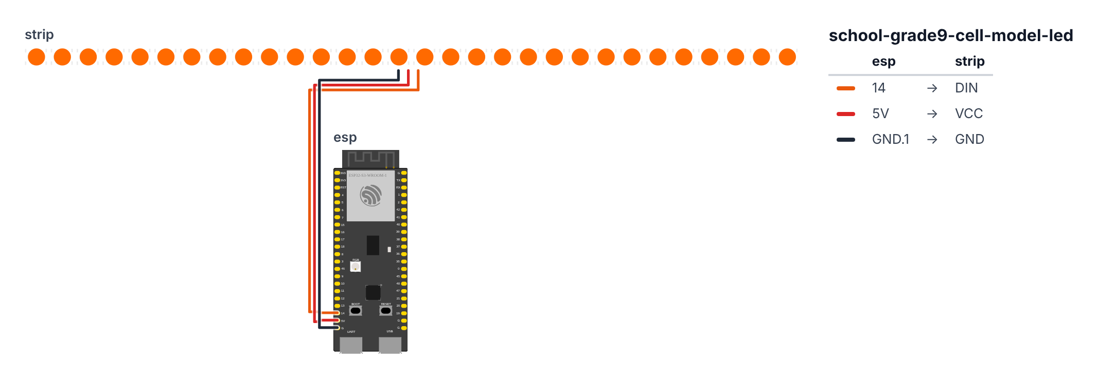
Only 3 wires to connect the LED strip to the ESP32.
- Strip DIN (data in) → board GPIO 14 (C6: GPIO 8) — orange wire. On the C6, GPIO 8 also drives the board’s own RGB LED, so that little LED copies the strip’s first LED (the nucleus). That’s normal.
- Strip VCC (5V) → board 5V pin — red wire
- Strip GND → board GND — black wire
Check: Three wires total. DIN goes to GPIO 14 (C6: GPIO 8), not DOUT. VCC goes to the 5V pin (not 3.3V — this strip needs 5V).
Step 2: Flash the code
Time: ~15 minutes
Open Arduino IDE. Install these libraries first:
- FastLED (by Daniel Garcia) — search in Library Manager
The big picture first. This program makes each LED behave like its organelle:
- The nucleus glows steady blue — the control center never sleeps.
- The mitochondria pulse red — they are constantly producing energy.
- The ribosomes flicker randomly — they are building proteins all the time.
- The cell membrane breathes slowly — it is always actively controlling what enters and exits.
A program is like a recipe. The computer reads it top to bottom and does exactly what is written, nothing more. Copy this entire recipe into Arduino IDE and upload it:
// ========== CHOOSE YOUR BOARD ==========
// Uncomment the line for YOUR board:
#define BOARD_S3    // ESP32-S3-DevKitC-1
//#define BOARD_C6  // ESP32-C6-DevKitC-1
// ========================================

#ifdef BOARD_S3
  #define PIN_LED   14
#endif
#ifdef BOARD_C6
  #define PIN_LED    8
#endif

#include <WiFi.h>
#include <FastLED.h>

#define NUM_LEDS    30
#define BRIGHTNESS  80

CRGB leds[NUM_LEDS];

const char* ssid = "YOUR_WIFI_NAME";
const char* password = "YOUR_WIFI_PASSWORD";

void setup() {
  FastLED.addLeds<WS2812B, PIN_LED, GRB>(leds, NUM_LEDS);
  FastLED.setBrightness(BRIGHTNESS);
  Serial.begin(115200);
  showRestingCell();
}

void loop() {
  leds[0] = CRGB(0, 0, 180);

  int pulse = (sin(millis() / 1000.0) + 1) * 127;
  leds[1] = CRGB(pulse, 0, 0);
  leds[2] = CRGB(pulse, 0, 0);

  for (int i = 6; i <= 9; i++) {
    if (random(10) > 7) leds[i] = CRGB(180, 120, 0);
    else leds[i] = CRGB(100, 70, 0);
  }

  for (int i = 3; i <= 4; i++) {
    int wave = (sin(millis() / 800.0 + i * 0.5) + 1) * 80;
    leds[i] = CRGB(0, wave + 30, 0);
  }

  if ((millis() / 3000) % 2 == 0) leds[5] = CRGB(180, 180, 0);
  else leds[5] = CRGB(40, 40, 0);

  leds[10] = CRGB(0, 60, 60);

  int lyso = (sin(millis() / 1500.0) + 1) * 60;
  leds[11] = CRGB(lyso, 0, lyso);
  leds[12] = CRGB(lyso, 0, lyso);

  int membrane = (sin(millis() / 2000.0) + 1) * 40 + 20;
  for (int i = 13; i <= 20; i++) {
    leds[i] = CRGB(membrane, membrane, membrane);
  }

  FastLED.show();
  delay(30);
}

void showRestingCell() {
  fill_solid(leds, NUM_LEDS, CRGB(10, 10, 10));
  FastLED.show();
  delay(500);
}

void showMitosis() {
  for (int round = 0; round < 3; round++) {
    for (int i = 0; i < NUM_LEDS; i++) {
      leds[i] = CRGB(200, 200, 200);
      FastLED.show();
      delay(50);
    }
    fill_solid(leds, NUM_LEDS, CRGB(0, 0, 0));
    FastLED.show();
    delay(200);
  }
}
Line-by-line: what every line does and why
Lines 1–2: Borrowing ready-made instruction books
#include <WiFi.h>
#include <FastLED.h>
#include means “grab this instruction book.” FastLED is a library — a huge set of pre-written instructions for controlling “smart” LEDs. Without it, making one LED glow a specific color would take hundreds of lines. With it, it takes one line.
Lines 4–6: Giving numbers easy names
#define PIN_LED   14
#define NUM_LEDS    30
#define BRIGHTNESS  80
#define is like writing a nickname on a sticky note. The data wire from the LED strip is plugged into leg 14 (C6: leg 8). There are 30 LEDs total. Brightness 80 out of 255 is about 30% — bright enough to see, dim enough not to blind anyone. If you want brighter, change 80 to 150.
Line 8: Creating the LED array
CRGB leds[NUM_LEDS];This creates a shelf with 30 compartments, one per LED. Each compartment holds a color — a mix of red, green, and blue values. CRGB is the color type. leds[0] is LED number 1, leds[1] is LED number 2, and so on.
Lines 16–21: setup() runs once when you power on
FastLED.addLeds<WS2812B, PIN_LED, GRB>(leds, NUM_LEDS);
FastLED.setBrightness(BRIGHTNESS);
Serial.begin(115200);
showRestingCell();
FastLED.addLeds<WS2812B, PIN_LED, GRB>(leds, NUM_LEDS) tells FastLED: “I have WS2812B LEDs, they are on leg 14 (C6: leg 8), they use GRB color order, and there are 30 of them.” setBrightness(80) sets a global brightness cap — like a dimmer switch for the whole strip. Serial.begin(115200) opens the phone line to your computer. showRestingCell() calls our starting animation (all LEDs dim).
Lines 23–69: loop() — the cell’s heartbeat
void loop() runs over and over, about 30 times per second. Each time through, it updates every organelle.
leds[0] = CRGB(0, 0, 180);Set LED #0 to blue: red=0, green=0, blue=180. This is the nucleus — steady, unchanging. The nucleus contains DNA and does not blink because DNA does not turn on and off.
int pulse = (sin(millis() / 1000.0) + 1) * 127;
leds[1] = CRGB(pulse, 0, 0);
leds[2] = CRGB(pulse, 0, 0);
This makes the mitochondria pulse. Here is the trick: millis() is a stopwatch counting milliseconds since power-on. sin() is a math function that goes up and down smoothly between -1 and +1 — like a wave. (sin(...) + 1) * 127 shifts it to go from 0 to 254 instead. So pulse smoothly cycles 0 → 254 → 0 → 254 every second. That number becomes the red channel — so the LED glides from dark to bright red and back. This simulates ATP energy production, which is constant and rhythmic.
for (int i = 6; i <= 9; i++) {
  if (random(10) > 7) leds[i] = CRGB(180, 120, 0);
  else leds[i] = CRGB(100, 70, 0);
}
for repeats for LEDs 6, 7, 8, and 9 — the ribosomes. random(10) picks a random number from 0 to 9. If it is greater than 7 (30% chance), the ribosome glows bright gold; otherwise it glows dim gold. This random flicker looks like protein assembly happening at random moments — which is biologically accurate.
for (int i = 3; i <= 4; i++) {
  int wave = (sin(millis() / 800.0 + i * 0.5) + 1) * 80;
  leds[i] = CRGB(0, wave + 30, 0);
}
The endoplasmic reticulum gets a green wave. The i * 0.5 shifts each LED slightly out of phase — so LED 3 and LED 4 do not pulse at exactly the same time, creating a flowing wave effect. wave + 30 adds a minimum brightness so the ER never goes completely dark.
if ((millis() / 3000) % 2 == 0) leds[5] = CRGB(180, 180, 0);
else leds[5] = CRGB(40, 40, 0);
The Golgi apparatus blinks every 3 seconds. millis() / 3000 gives the number of 3-second intervals elapsed. % 2 gives the remainder after dividing by 2 — it alternates between 0 and 1. When 0: bright yellow. When 1: dim yellow. This represents the Golgi “packaging” proteins in bursts.
int membrane = (sin(millis() / 2000.0) + 1) * 40 + 20;
for (int i = 13; i <= 20; i++) {
  leds[i] = CRGB(membrane, membrane, membrane);
}
The cell membrane LEDs all breathe together in white. A 2-second sine wave gives a slow, calm rhythm. Equal red, green, and blue values always produce white (or grey when dim). This simulates the membrane’s constant selective permeability — always active, never static.
FastLED.show();
delay(30);
FastLED.show() is the most important line — it pushes all the color data you just calculated out to the physical LEDs. Without this, every change you made to the leds[] array stays invisible. delay(30) waits 30 milliseconds before the next frame — giving about 33 animation frames per second, which looks smooth to the human eye.
Lines 71–75: showRestingCell() — the startup state
void showRestingCell() {
  fill_solid(leds, NUM_LEDS, CRGB(10, 10, 10));
  FastLED.show();
  delay(500);
}
fill_solid() sets every LED to the same color at once — CRGB(10, 10, 10) is a very dim white, like a cell at rest. This runs once at startup so the cell does not flash bright before the animation begins.
Lines 77–89: showMitosis() — cell division animation
void showMitosis() {
  for (int round = 0; round < 3; round++) {
    for (int i = 0; i < NUM_LEDS; i++) {
      leds[i] = CRGB(200, 200, 200);
      FastLED.show();
      delay(50);
    }
    fill_solid(leds, NUM_LEDS, CRGB(0, 0, 0));
    FastLED.show();
    delay(200);
  }
}
Two nested loops. The outer for (round) runs 3 times. The inner for (i) lights up LEDs one by one with a 50ms delay each — creating a sweep of light across the whole cell. Then fill_solid(..., CRGB(0,0,0)) turns everything black (off). Three sweeps simulate the dramatic reorganization of cell division.
The whole thing in one sentence
When powered on, all LEDs start dim (showRestingCell). Then loop runs endlessly — every 30 milliseconds it recalculates each organelle’s color based on math waves and random numbers, then pushes everything to the LEDs with FastLED.show().
First thing to try: Find the line int pulse = (sin(millis() / 1000.0) + 1) * 127; and change 1000.0 to 200.0. Re-upload. The mitochondria will pulse 5 times faster. Then change it back. This is how you control animation speed — the number inside millis() / X is the period in milliseconds.
Select board: ESP32S3 Dev Module. Upload. Watch the organelles light up.
Check: Open Serial Monitor at 115200 baud. You should see “Cell model ready” printed. All organelles should show their assigned colors.
Step 3: Calibrate organelle positions
Time: ~10 minutes
Run this calibration sketch first to identify which physical LED number is which organelle:
In loop(), temporarily replace everything with:
// Light one LED at a time so you can label them
int current = (millis() / 2000) % NUM_LEDS;
fill_solid(leds, NUM_LEDS, CRGB(0,0,0));
leds[current] = CRGB(255, 0, 0);
FastLED.show();
Serial.println("LED: " + String(current));
One LED lights up every 2 seconds. Write down which physical location each number corresponds to, then update the LED number table from Step 0 to match.
Step 4: Present it!
Time: your science fair / class period
During your presentation:
- Start with resting cell (dim, slow pulse)
- Explain each organelle — point to it, it reacts
- Say “the cell is working hard” — trigger the mitosis animation
- Ask your teacher: “Can you guess which organelle is the powerhouse?”
Presentation tip: Prepare a 30-second “compare” moment — hold up a plain poster next to your cell. Say: “Every organelle on this poster is just labeled. Every organelle in my model is actually behaving like the real thing does — the mitochondria pulse because they’re generating energy, not just sitting there.”
What just happened
You used PWM signals to create brightness variations — the same technique used in TV backlights and stage lighting. Each “pulse” in the mitochondria is a sine wave: sin(time) → brightness. That’s math running in real hardware.
Curriculum connections:
- NGSS HS-LS1-1: Construct an explanation based on evidence for how the structure of DNA determines the structure of proteins
- NGSS MS-LS1-2: Develop and use a model to describe the function of a cell as a whole and ways the parts of cells contribute to the function
- AP Biology: Cell structure and function, organelle roles in metabolism
The flickering ribosomes model the fact that ribosomes are not static — they’re constantly assembling proteins. The pulsing mitochondria reflect that ATP production is a continuous cycle. Your model is more accurate than a poster.
Level Up
Add a button to trigger mitosis: Wire a button to GPIO 0 (C6: GPIO 9) — that’s the pin the BOOT button already uses. When pressed, run showMitosis(). Now anyone can “start cell division” during your presentation.
Plant cell version: Change the cell membrane LEDs to green (chloroplasts on the outside). Add a chloroplast organelle (bright green) that only activates when a light sensor detects light — simulating photosynthesis.
Compare animal vs. plant: Build two cells side by side. Plant cell has chloroplasts + rigid membrane (green outer ring). Animal cell has centrioles + flexible membrane.
Troubleshooting
| Problem | Fix |
|---|---|
| LEDs don’t light at all | Check DIN is on GPIO 14 (C6: GPIO 8), not DOUT. Check 5V pin (not 3.3V). Try plugging power bank directly to VCC/GND. |
| Colors look wrong (red shows as green) | Change GRB to RGB in FastLED.addLeds<WS2812B, PIN_LED, GRB> |
| Some LEDs don’t respond | Strip has a break — cut at the break, reconnect with jumper wire. |
| Flickering/random colors | Add a 100–470Ω resistor on the DIN wire. |
| Upload fails | Hold BOOT button on ESP32 while clicking Upload. |